


RFL 9508 PLC-TT
RFL Electronics Inc.
September 5, 2012
11
(973) 334-3100
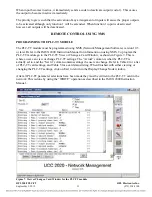
FUNCTIONAL DESCRIPTION
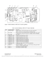
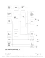
The following is a basic description of how the RFL PLC-TT module operates. A simplified block
diagram of the module appears in Figure 5.
SYSTEM OVERVIEW
The PLC-TT module is a channel card for use in the RFL 9508 system. It transmits and receives data
via the T1/E1 serial link and generates and receives trip commands via an I/O adapter module. Up to
four trip inputs and four trip outputs can be supported. The module can be setup and interrogated
remotely via the SCB of the 9508. Front panel LEDs indicate the status of the trip inputs and outputs.
A real time clock with sequence of events storage is also available.
The module consists of three major sections. The microcontroller section contains an 80C320
embedded microcontroller and associated support devices. The trip FPGA (field programmable gate
array) and its associated circuits handles all T1/E1 communication and trip I/O. The SCB FPGA
connects the processor with the SCB of the 9508. Miscellaneous other circuits are present to handle
other functions. A switch is provided to disable the card for removal and insertion, and a jumper is
provided to select between relay and solid state outputs.
MICROCONTROLLER CIRCUIT
The heart of the microcontroller circuit is an 80C320 8 bit embedded microcontroller. Its main purpose
is to control the setup and interrogation functions of the transfer trip module. It does not do any
processing of the T1/E1 data and trip signals. A PSD312 programmable device provides 2KB of RAM,
64KB of ROM, and port reconstruction for the 80C320. It is connected to ports 0 and 2 of the
microcontroller. A DS1642 device provides non volatile RAM, a real time clock function, and contains
an embedded clock and battery. A MAX691 device provides a reset pulse on power turn on and a
watchdog timer function.
TRIP FPGA CIRCUIT
The trip FPGA interfaces directly with the T1/E1 bus of the 9508 chassis. It is also connected to the
trip inputs and outputs.
SCB FPGA CIRCUIT
The SCB FPGA circuit is used to communicate with the CM4 via the SCB. The transfer trip module
type ID of 118 is encoded into the SCB FPGA device.


