


Configuration
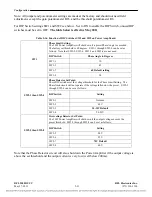
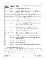
Table 5-19. Line Board Setup Jumpers and Switch Setting
Reference
Designation
Component Function
J10
Jumper
Used to set Rx Impedance of 4W systems.
Can be set to 50, 75, 100 or 130 Ohms for 103090 module.
Can be set to 50, 75, 100 or 150 Ohms for 103090-1 module.
J20
Jumper
Used to set Tx Impedance of 4W systems or the Tx & Rx Impedance of
2W systems.
Can be set to 50, 75, 100 or 130 Ohms for 103090 module.
Can be set to 50, 75, 100 or 150 Ohms for 103090-1 module.
J1-J9
Jumper
Adjusts capacitive component of line impedance.
Refer to the Hybrid Tuning procedure in paragraph 6.2.5.1
J15-J17,
J18-19, J21
and J22
Jumper
Adjusts inductive component of line impedance
Refer to the Hybrid Tuning procedure in paragraph 6.2.5.1
R1 Potentiometer
Adjusts
resistive component of line impedance.
Refer to the Hybrid Tuning procedure in paragraph 6.2.5.1
S1
Switch
A 6-position rotary switch, which allows the selection of various resistors to
adjust the resistive component of the line impedance.
Refer to the Hybrid Tuning procedure in paragraph 6.2.5.1
J28
Jumper
Install this jumper in the TOP position if the attenuator module is not
equipped. Install it in the BOTTOM position if the attenuator module is
equipped.
J25
Jumper
Selects 4W mode or Loopback mode.
J11, J12 and
J23
Jumper
All three of these jumpers must be set to 2W to select 2W mode.
All three of these jumpers must be set to 4W to select 4W mode.
R10
Potentiometer Adjusts the Rx Output level. See paragraph 6.2 for adjustment procedure.
TP1
Test point
Connect the low or common side of test equipment to this test point when
monitoring TP2 or TP3.
TP2
Test point
Tx monitor high, test point.
TP3
Test point
Rx monitor high, test point.
J16
Jumper
Used for factory testing. In normal operation this jumper is not installed.
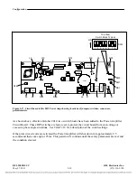
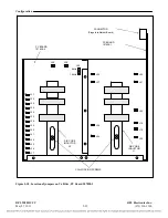
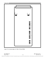
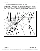
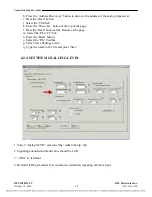
5.3.2.5
ATTENUATOR BOARD SETTINGS
The Attenuator Board has one toggle switch (SW1) that must be set for proper system operation. The
toggle switch SW1 selects either Normal or Loopback operation. In Normal operation, set the switch to
the DOWN position. In Loopback operation set to switch to the UP position. The switch location is
shown in Figure 7-13, and is accessible when the Attenuator Board is plugged into the chassis.
RFL 9508D UCC
RFL Electronics Inc.
May 27, 2011
5-39
(973) 334-3100


