


●
Connect the equipment grounding conductor of the components of the
electric drive and control system permanently to the main power supply
at all times. The leakage current is greater than 3.5 mA.
●
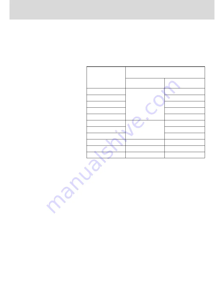
Establish an equipment grounding connection with a minimum cross
section according to the table below. With an outer conductor cross sec‐
tion smaller than 10 mm
2
(8 AWG), the alternative connection of two
equipment grounding conductors is allowed, each having the same
cross section as the outer conductors.
Cross section outer con‐
ductor
Minimum cross section equipment grounding conductor
Leakage current ≥ 3.5 mA
1 equipment grounding
conductor
2 equipment grounding
conductors
1,5 mm
2
(AWG 16)
10 mm
2
(AWG 8)
2 × 1,5 mm
2
(AWG 16)
2,5 mm
2
(AWG 14)
2 × 2,5 mm
2
(AWG 14)
4 mm
2
(AWG 12)
2 × 4 mm
2
(AWG 12)
6 mm
2
(AWG 10)
2 × 6 mm
2
(AWG 10)
10 mm
2
(AWG 8)
-
16 mm
2
(AWG 6)
16 mm
2
(AWG 6)
-
25 mm
2
(AWG 4)
-
35 mm
2
(AWG 2)
-
50 mm
2
(AWG 1/0)
25 mm
2
(AWG 4)
-
70 mm
2
(AWG 2/0)
35 mm
2
(AWG 2)
-
...
...
...
Fig.1-1:
Minimum Cross Section of the Equipment Grounding Connection
1.1.3
Protection Against Dangerous Movements
Dangerous movements can be caused by faulty control of connected motors.
Some common examples are:
●
Improper or wrong wiring or cable connection
●
Operator errors
●
Wrong input of parameters before commissioning
●
Malfunction of sensors and encoders
●
Defective components
●
Software or firmware errors
These errors can occur immediately after equipment is switched on or even
after an unspecified time of trouble-free operation.
The monitoring functions in the components of the electric drive and control
system will normally be sufficient to avoid malfunction in the connected
drives. Regarding personal safety, especially the danger of injury and/or
property damage, this alone cannot be relied upon to ensure complete safety.
Until the integrated monitoring functions become effective, it must be as‐
sumed in any case that faulty drive movements will occur. The extent of faulty
drive movements depends upon the type of control and the state of opera‐
tion.
DOK-INDRV*-HCS03******-IT01-EN-P
Rexroth IndraDrive Drive Controllers Power Sections HCS03
Bosch Rexroth AG
15/67
Important Notes