


Revision 1.1
Page 15 of 21
Warning
Please Note
The specifications of the product detailed on this
Set-Up Guide may change without notice. RDM
Ltd. shall not be liable for errors or for incidental
or consequential damages, directly and indirectly,
in connection with the furnishing, performance or
misuse of this product or document.
Ensure that all power is
switched off before
installing or maintaining
this product
Mercury 2 & Intuitive Mobile Controller User Guide
www.resourcedm.com
IP-r
To configure the communication module for IP-r, set the three rotary switches to give each controller a unique identifier. The module
should then be connected to the controller and the network. In the case of an Intuitive Mercury controller where the network card is
already fitted, the three rotary switches must be set when the controller is powered off, the controller should then be powered on to
connect to the network.
2.
nEt. From the function menu you can now select nEt
Press en
ter and the display will show “IP-r”, press enter
You can now view only the address given by the DHCP server
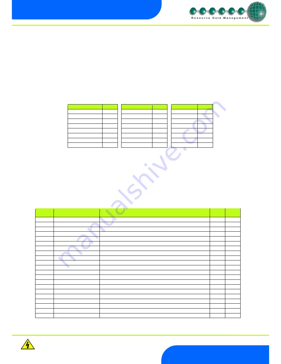
To ease setup, a single network mask length value is used. If the address has been specified with a network mask value in dotted IP
format e.g. 255.255.255.0 then the table below gives the conversion:
Mask
Length
Mask
Length
Mask
Length
255.255.254.0
23
255.254.0.0
15
255.255.255.252
30
255.255.252.0
22
255.252.0.0
14
255.255.255.248
29
255.255.248.0
21
255.248.0.0
13
255.255.255.240
28
255.255.240.0
20
255.240.0.0
12
255.255.255.224
27
255.255.224.0
19
255.224.0.0
11
255.255.255.192
26
255.255.192.0
18
255.192.0.0
10
255.255.255.128
25
255.255.128.0
17
255.128.0.0
09
255.255.255.0
24
255.255.0.0
16
255.0.0.0
08
Mercury Switch
Please refer to the Mercury Switch user guide, which can be obtained from the RDM website, for information regarding connecting a
controller to a network.
Viewing
Apart from setting up the controller, you can also view the status of the inputs and outputs and controller states.
From the function menu, select “I/O”, press enter. You can now scroll through the IO table as set out below. Inputs and outputs that do
not apply to a particular controller type will be greyed out.
Input / Output Table
Number
IO
Range*
o
C (
o
F )
Step
Units
I-01
Control Temp.
-42 to 60 (-43.6 to 140)
0.1
Deg
I-02
Display temp
-42 to 60 (-43.6 to 140)
0.1
Deg
I-03
Air on Probe
-49 to 60 (-56.2 to 140)
0.1
Deg
I-04
Air off Probe
-49 to 60 (-56.2 to 140)
0.1
Deg
I-05
Comp A Discharge Probe
-42 to 60 (-43.6 to 140)
0.1
Deg
I-06
Comp B Discharge Probe
-42 to 60 (-43.6 to 140)
0.1
Deg
I-08
Logging Probe
-49 to 60 (-56.2 to 140)
0.1
Deg
I-09
Defrost Probe
-49 to 60 (-56.2 to 140)
0.1
Deg
I-10
Plant Fault 1
0 (OK), 1 (Alarm)
I-11
Case Clean
0 (Off), 1 (On)
I-14
Plant Fault 2
0 (OK), 1 (Alarm)
I-15
Monitor Probe
-49 to 60 (-56.2 to 140)
0.1
Deg
I-18
External Defrost
0 (Off), 1 (On)
I-20
Load Shedding
0 (Off), 1 (On)
O-03
Compressor A
0 (Off), 1 (On)
O-04
Compressor B
0 (Off), 1 (On)
O-05
Defrost Control
0 (Off), 1 (On)
O-06
Lights
0 (Off), 1 (On)
O-07
Case Fans
0 (Off), 1 (On)
O-10
Last Def. Time
00:00 to 23:59
hh:mm
O-11
Last Def. Length
00:00 to 03:00
hh:mm


