19
│
Sentinel Kinetic Advance S, SX - www.regulus.eu
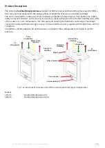
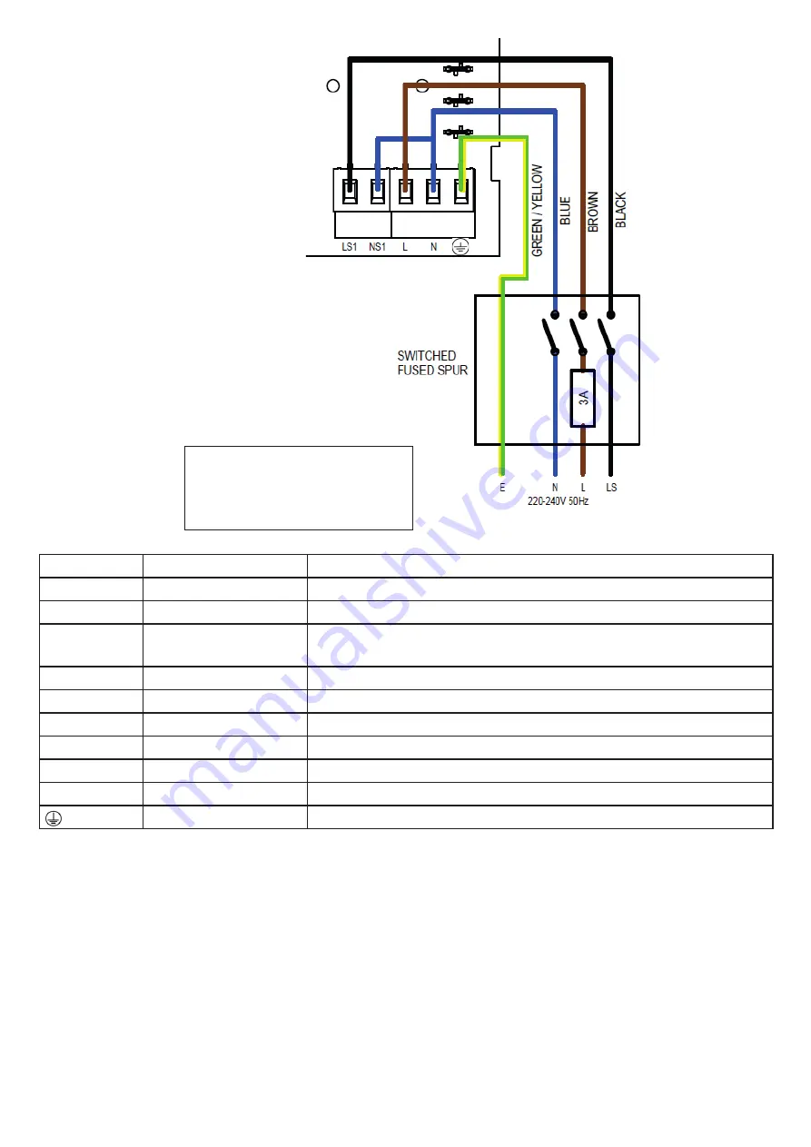
Table 1: Terminal Connections
Terminal No. Name
Description (Control Mode 01)
REMOTE
Remote
Terminals for connecting a remote external to the unit
SWI
Switch 1
Volt-free contact for sensor input b and - terminals
LED
Red Light Emitting
Diode Output
A 5 V LED driving signal output between the + and – terminals that
enables remote indication of a unit fault.
DIAG
Diagnostic
Diagnostic port
USB
USB
Commissioning port
LS1
Switched Live
220-240 V AC, 50 Hz input
NS1
Switched Neutral
220-240 V AC, 50 Hz input
L
Mains Live
220-240 V AC, 50 Hz input
N
Mains Neutral
220-240 V AC, 50 Hz input
EARTH
Mains Earth
Earth connector
Other means of connecting the
unit may be used if they meet
the local wiring regulations.
SEE NOTES ON PAGE 20

