3
Tighten feed screw.
RC30S in use
with FPV20 vise.
Saddle held in
place by chain.
Saddle holds
ratchet handle.
CAUTION:Always wear
proper eye protection
when using this or any
hand tool.
hammer and chisel or coarse file may also be used. This will help
save cutter wheels and cutting time; and helps to square the cutter
on the pipe to ensure tracking.
HELPFUL HINTS:
On large diameter pipe, it may be desirable
to alternate two workers pulling on the handle. Failure to maintain
maximum preassure only results in wasted time. While cast and
ductile iron pipe will fracture along the cut line after penetrating part
way, continue feeding the wheels in to make sure the cut is com-
pleted. Ductile iron tends to work harden. Continuous feeding and
maximum pressure helps prevent this. If some ductile iron needs to
be cut all the way through, consider using cutter wheels for steel, as
they will cut much faster. The steel cutter wheels will not last as long
as cutter wheels for ductile, and may be only effective on less hard
ductile iron.
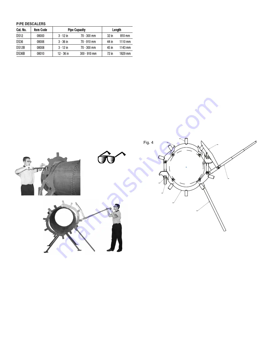
OPERATING INSTRUCTIONS for RC30,
RC36, and RC42 Rotary™ Cutters
To aid in rotating cutters RC30 and larger, a Ratcheting Mechanism
is included with each cutter. This mechanism consists of a saddle
(or pivot block) that is clamped to the pipe by a chain, a lever handle
and a latch (Figs 4 and 5). As the handle is rotated up, the latch
slides up over the top of a lug on the cutter. When the handle is
rotated down, the latch engages the lug and pulls the cutter around
the pipe.
1. Place upper yoke half (the one with finger guides) on the top
of the pipe. Be sure the round grooves in the lugs are
facing away from the direction of rotation. Align the wheels
over desired cutting line.
2. Attach lower yoke to upper yoke one side at a time by sliding
the main screws into the slots and seating the nuts into
counter bores.
3. Check to see if cutter wheels are over desired cutting line.
Rotate the cutter until the weight of the cutter is resting on
the spring-loaded guide fingers and the two guides are
centered on the top of the pipe. All cutter wheels should at this
time be away from the pipe.
4. Slightly rock and wiggle the cutter until all four of the guide
fingers touch the pipe. This process insures the cutter sits
square on the pipe. Check to see if cutter wheels are centered
over desired cutting line.
5. Next, without disturbing the cutter position, tighten up the
main screw nuts EQUALLY by hand. Usually the two
bottom wheels will contact the pipe first. Continue
tightening as the spring-loaded guide fingers retract and
permit the top wheels to contact the pipe. Using the wrench,
tighten the one accessible nut as tight as possible while still
being able to rotate the cutter.
6.
Set-up for Ratcheting Mechanism
Insert Torque Arm into saddle. Place the saddle on the side
of cutter where the pipe is to remain. Rest the teeth of the
saddle against the pipe and the Torque Arm against the
ground at an angle. Adjust the position of the saddle so
that it is 3-1/8” (79 mm) from the center of cut to the side
of saddle (Fig. 6). Be sure all four teeth of the saddle are
contacting the pipe for proper alignment. Loosen chain
screw nut to the end of the screw, wrap the chain around the
pipe and pull tight. Hook closest chain link into the chain catch
on the opposite end of the saddle. Fully tighten the chain
screw with the provided wrench.
7. Connect ratchet handle to the triangular saddle by inserting
the lower steel pin on the end of the handle into the hole in
the saddle. Secure the handle with the washer and cotter pin
provided.
8. Connect red latch (used to hook around lugs) to ratchet
handle pin. Secure the latch with the other washer and cotter
pin provided. Check to see if the latch is centered over the
cutter.
RATCHETING MECHANISM
GUIDES
LUG
LATCH
HANDLE
TORQUE ARM
MAIN SCREW
NUT
MAIN CUTTER
Fig. 3
NOTE: Check Fig. 7 to see proper RC42 cutter pivot pin position.


