22
8. Operation
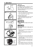
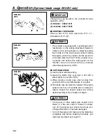
lever is in to the “start” position. (OP6)
6. While holding the unit firmly, pull out the starter
rope quickly until engine fires. (OP7)
(1) choke lever (2) close (3) open
(4) ignition switch (5) start (6) stop
(7) throttle set button
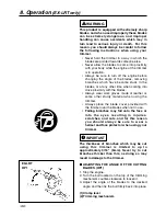
The product is equipped with a centrifugal
clutch mechanism, so the cutting attachment
begins to rotate as soon as the engine is
started by pulling the throttle. When starting
the engine, place the product onto the ground
in a flat clear area and hold it firmly in place so
as to ensure that neither the cutting part nor
the throttle come into contact with any obstacle
when the engine starts. (OP8)
• Avoid pulling the rope to its end or returning it by
releasing the knob. Such actions can cause
starter failures.
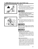
7. Move the choke lever downward to open the
choke. And restart engine. (OP5)
8. Allow the engine to warm up for a several
minutes before starting operation.
1. When restarting the engine immediately after
stopping it, leave the choke open.
2. Overchoking can make the engine hard to start
due to excess fuel. When the engine failed to
start after several attempts, open the choke and
repeat pulling the rope, or remove the spark plug
and dry it.
■
STOPPING ENGINE (OP6)
1. Release the throttle lever and run the engine for
a half minute.
2. Shift the ignition switch to the STOP position.
NOTE
IMPORTANT
WARNING
(4)
(7)
(5)
(6)
OP6
OP7
OP8
Summary of Contents for EXtreme EX-HE
Page 46: ...12 Parts list 46 Fig 1 EXZ PU S N 60300000 and up...
Page 48: ...12 Parts list 48 Fig 2 EX2 BC S N 50200000 and up...
Page 50: ...Fig 3 ENGINE UNIT 60100000 and up 50 12 Parts list...
Page 52: ...12 Parts list 52 Fig 4 EX LRT S N 000531 and up...
Page 54: ...12 Parts list 54 Fig 5 EX PS S N 000000 and up...
Page 56: ...12 Parts list 56 Fig 6 EX HE S N 000101 and up...

