18
6. Set up
(EX-HE only)
EX-HE
SE1
EX-HE
SE2
EX-HE
SE3
EX-HE
SE4
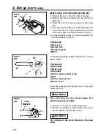
1. Insert the driveshaft into the clutch drum, then
attach the gearbox to the shaft tube as aligning
the positioning holes. Wipe out grease on the
tube and the inside of the gearbox. Screw in the
lock screw and fasten the clamp bolt firmly.
(SE1)
(1) Clamp bolt
(2) Lock screw
2.Install the blade guard to the gear case with the
provided 3 screws, then clamp it to the shaft
tube with 2 screws. (SE2)
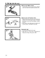
3.Place the blade between the cutter holders (A)
and (B) while locking the gear shaft by putting
the bar, one of the tools provided, through the
key holes on the holder(A) and the gearcase.
Use the socket and the screwdriver as shown in
the picture below to tighten the blade mounting
bolt. (SE3)
(1) Blade mounting bolt (Left-handed)
(2) Cutter holder (B)
(3) Blade
(4) Bar
(5) Cutter holder (A)
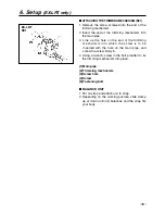
4.Split the bracket and install the wheel assembly
to the shaft tube and clamp at a position best for
your job. (SE4)
(1) Bracket
Summary of Contents for EXtreme EX-HE
Page 46: ...12 Parts list 46 Fig 1 EXZ PU S N 60300000 and up...
Page 48: ...12 Parts list 48 Fig 2 EX2 BC S N 50200000 and up...
Page 50: ...Fig 3 ENGINE UNIT 60100000 and up 50 12 Parts list...
Page 52: ...12 Parts list 52 Fig 4 EX LRT S N 000531 and up...
Page 54: ...12 Parts list 54 Fig 5 EX PS S N 000000 and up...
Page 56: ...12 Parts list 56 Fig 6 EX HE S N 000101 and up...


