Doc. #70-00058-01-01-DRAFT
Proprietary Redline Communications © 2006
November 29, 2006
Page 1 of 106
Red
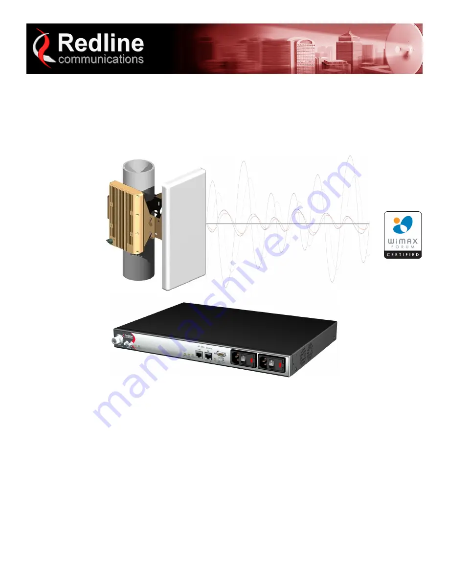
MAX
TM
AN-100U Single Sector
Wireless Access Base Station
User Manual
Page 1: ...Doc 70 00058 01 01 DRAFT Proprietary Redline Communications 2006 November 29 2006 Page 1 of 106 RedMAX TM AN 100U Single Sector Wireless Access Base Station User Manual...
Page 2: ...Control 70 00058 01 01 RedMAX_BaseStn_UserMan_100U 20061128a doc Disclaimer The statements configurations technical data and recommendations in this document are believed to be accurate and reliable...
Page 3: ...Overview 17 2 1 Introduction 17 2 2 IEEE 802 16 WiMAX Compliance 18 2 3 PHY Specification 18 2 4 OFDM 256 FFT 18 2 5 Features 18 2 5 1 Privacy 18 2 5 2 Time Division Duplexing TDD 19 2 5 3 Coding Rate...
Page 4: ...27 Data Port 100 LED 27 Data Port FD Col LED 27 Mgt Port 27 Mgt Port LEDs 27 Mgt Port Link Link Act LED 27 Mgt Port Act 100 LED 28 3 1 5 System Section 28 System LEDs 28 System Pwr LED 28 System Faul...
Page 5: ...ice Flows 47 Service Flow Configuration Screen 47 Add Service Flow 47 Delete SF all associated Classifiers is deleted 48 Service Flows 48 4 3 4 Classifiers 50 Classifier Configuration Screen 51 Add a...
Page 6: ...er 68 Delete User 69 User Accounts 69 5 CLI Interface 70 5 1 Connecting via Telnet 70 Telnet Logout 70 5 2 CLI Modes 71 5 2 1 Common Controls 71 5 3 CLI Command 71 5 3 1 interfaces 72 5 3 2 ipAddress...
Page 7: ...2 Console Port 85 7 2 3 System Reset Switch 85 7 3 Replacing the System Fuse 85 7 4 Recovering a lost IP address 86 7 5 Re Ranging Log Message 86 7 6 Troubleshooting the Web Interface 86 7 7 RF Troubl...
Page 8: ...Screens and Access Control 32 Table 17 System Wireless Channel Selection 3 4 3 6 55 Table 18 Web Wireless Adaptive Modulation Threshold Settings 62 Table 19 CLI Root Mode Commands 71 Table 20 CLI Com...
Page 9: ...tus Wireless Statistics Screen 36 Figure 17 Web Monitoring SS Info Screen 38 Figure 18 Web Monitoring SS Info SF Info Screen 39 Figure 19 Web Monitoring Event Log Screen 40 Figure 20 Configuration Ser...
Page 10: ...ng and safety instructions 2 Installation of the antenna and transceiver must be contracted to a professional installer 3 This product is supplied with a grounding power plug Do not defeat this import...
Page 11: ...esponsibility to install this device in accordance with the local electrical codes correct installation procedures for grounding of the transceiver unit mast lead in wire and discharge unit location o...
Page 12: ...9 5 EF Hierbij verklaart Redline Communications dat het toestel RedMAX Base Station model base station in overeenstemming is met de essenti le eisen en de andere relevante bepalingen van richtlijn 199...
Page 13: ...se station cumple con los requisitos esenciales y cualesquiera otras disposiciones aplicables o exigibles de la Directiva 1999 5 CE Swedish H rmed intygar Redline Communications att denna RedMAX Base...
Page 14: ...performance PA1690EAS Premium Sector Antenna 90 degree 16 dBi High performance sector antenna vertical polarization offers improved cross polarization and F B performance PA1590EASH Premium Sector An...
Page 15: ...rranty is valid only if the Redline approved IF cable is installed and properly weatherproofed according to instructions in the base station Installation Guidelines manual Doc 70 00059 01 XX Refer to...
Page 16: ...D FOR THE PRICE OF THE PRODUCT FOR ANY PRODUCT RETURNED TO REDLINE THAT IS DEEMED TO HAVE FAILED AS A RESULT OF AN ACT OF GOD OR MODIFICATIONS NOT MADE BY REDLINE 1 8 WEEE Product Return Process Figur...
Page 17: ...base station Terminal Transceiver and Antenna The base station consists of an indoor terminal IDU and outdoor transceiver and antenna ODU Each operational RedMAX wireless broadband network segment is...
Page 18: ...m and is participating in interoperability testing in the WiMAX Forum 2 3 PHY Specification The base station is designed for 2 11 GHz operation based on the WirelessMAN OFDM PHY definition in the IEEE...
Page 19: ...ation making it more resistant to potential over the air errors The coding rate is the ratio of user data to the total data transmitted including the redundant error correction data The base station s...
Page 20: ...deployments typically use a directional narrow beam antenna for both ends of the link Figure 3 System PTP Line of Sight Deployment 2 6 2 PMP Deployment When deployed in a PMP configuration the base st...
Page 21: ...ne of Sight Deployment 2 6 4 Channelization The base station is a frequency specific system with the frequency band defined by the transceiver unit The use of the operating band must be in accordance...
Page 22: ...rection 2 A 16 bit Connection ID CID is associated with each active SFID connection active 3 A set of QoS parameters specifying the required resources The principal resource is bandwidth but the speci...
Page 23: ...usly changing bandwidth requirements Non Real Time Polling Service nrt PS The base station schedules regular transmit opportunities for the subscriber station to send variable size data packets Typica...
Page 24: ...lowest nrtPS first and then BE 2 Traffic Priority setting from highest 7 to lowest 0 when there are multiple service flows of the same service type Wireless transmission bandwidth is optimized by gran...
Page 25: ...at the rear of the terminal 3 1 1 Mounting The terminal can be freestanding on a flat surface or mounted into a standard 19 inch equipment rack 3 1 2 Power Supply Power supply options include single...
Page 26: ...t indicator This indicates proper communication with the outdoor unit ODU and that the framer is operating correctly If this LED is not flashing there is no possibility of establishing a wireless link...
Page 27: ...FF LAN is operating at 10 Mbps Data Port FD Col LED The FD Col LED lights green when the port is operating in Full Duplex mode The LED flashes when collisions are detected Table 8 System Ethernet Data...
Page 28: ...her general features of the front panel System LEDs The System LEDs indicate power supply status and system faults Figure 9 System System LEDs and Reset Switch System Pwr LED The Pwr LED lights green...
Page 29: ...ults Refer to Troubleshooting section 3 1 6 Grounding Connection A ground terminal is located on the rear of the terminal Correct grounding is very important for safe operation of wireless equipment 3...
Page 30: ...rminal Transmits status information to the terminal Receives control information from the terminal Receives DC power from the terminal RF Port The transceiver RF port female N type connector is used f...
Page 31: ...ng functions can be performed using the web based interface described in detail in this chapter 4 1 System Menu When you login to the base station the General Information page is displayed A menu of a...
Page 32: ...and error messages Service Flow Configuration Subscribers X X Summary of registered subscribers Service Classes X X Define the set of service classes Service Flows X X Define service flows based on th...
Page 33: ...rough cable 3 Power on the base station terminal and restore the factory default settings by depressing the reset switch on the front panel for more than five 5 seconds 4 Launch a Web Browser on the P...
Page 34: ...r this base station Software Version Current version of software running on the base station Radio Type Identifies the transceiver type connected to this base station Refer to the Appendices for a lis...
Page 35: ...he subscriber change modulation rate RF Tx Power dBm Radio transmission output power level Traffic Downlink Kbps Rate of traffic transmitted to subscribers Traffic Uplink Kbps Rate of traffic received...
Page 36: ...ature Celsius Internal temperature of the transceiver Power Supply Status Display the status of the power circuits acOnly Terminal is equipped with AC circuits only dcOnly Terminal is equipped with DC...
Page 37: ...frames with a unicast destination address In Not Unicast Pkts Total number of received valid Ethernet frames with a multicast or broadcast destination address In Discards Total number of valid Etherne...
Page 38: ...remote management No The subscriber can not be managed remotely Channel Mod Modulation and coding settings DL Modulation and coding setting for downlink channel UL Modulation and coding setting for u...
Page 39: ...able to setup the service flow Requesting base station is attempting to setup the service flow Provisioned Time Time elapsed since this service flow became active CS Specification Classification type...
Page 40: ...6 November 29 2006 Page 40 of 106 4 2 4 Event Log Click Event Log in the menu left side of screen to view system activity and error messages recorded by the terminal Refer to section 7 8 System Log Me...
Page 41: ...ng service class definitions Separate service flows are required for downlink and uplink traffic Each definition requires identifying the subscriber flow direction class of service and the classifier...
Page 42: ...r Note When upgrading from RedMAX v1 0 this field will automatically be populated with the subscriber MAC address Max Hosts Number Enter the maximum number of MAC addresses to discover on the Ethernet...
Page 43: ...he upper portion of the screen These settings can be modified and used to create a new subscriber entry Click Add to create the new subscriber entry Edit Select a subscriber and click Edit to display...
Page 44: ...ame can be any combination of up to 30 letters and numbers Traffic Priority Enter the priority to be used for service flows created using this service class The priority is relative only to other serv...
Page 45: ...t regular intervals Required settings are Max Sustained Rate Min Reserved Rate Max Latency unsolicitedGrantService rtPS For applications requiring fixed length data packets issued at periodic interval...
Page 46: ...fic Prio Priority setting relative to other service flows on the same subscriber MaxSTR Maximum sustained traffic rate setting MinRR Minimum reserved rate setting MaxLat Maximum latency setting Fixed...
Page 47: ...ervice flow such as broadcast ARP between the base station and subscribers The default service flow capacity is 64 Kbps DL shared for all subscribers in the sector and limited to 8 Kbps UL for each su...
Page 48: ...w is deleted when the subscriber sends acknowledgement or becomes deregistered Service Flows Select Select the unique index number for the service flow to display Template Click Template to modify any...
Page 49: ...ss relative to when the base station was rebooted If required the absolute time and day of an event can be determined using the Time Since System Restart on the General Information page Current Time T...
Page 50: ...fiers become active after clicking the Add button on this screen When multiple classifiers are defined for one service flow the index number is listed in the form X Y where X Service Flow index SfId Y...
Page 51: ...all ones ff ff ff ff ff ff will match only the MAC address entered in the DestMacAddr field 2 A partially specified mask value will match a range of MAC addresses For example a mask value of 01 02 03...
Page 52: ...d The format is Service flow index Classifier index Delete Click Delete to permanently delete the selected classifier View Classifiers Service Flow Identifier Select index number of an existing servic...
Page 53: ...to 7 Low Lowest priority setting of range Hi Highest priority setting of range Mask A logical AND is performed using the mask and the ip tos value before testing for range SrcIp IPv4 source address Ad...
Page 54: ...es service flows or classifiers No Modifications Detected There are no unsaved changes Modifications Detected There are unsaved changes Save Click Save to save all changes Saving changes will copy all...
Page 55: ...to settings marked with a red asterisk are only effective after clicking the Save button and resetting the base station terminal Figure 25 Web Configuration Wireless Interface Screen RF Parameters RF...
Page 56: ...ons for that regulatory domain SS Tx Power Control Enable Check this box to allow the base station to automatically adjust the transmit power level of subscribers When enabled the base station continu...
Page 57: ...rnal GPS clock connection Slave This base station synchronizes its operations to the synchronization pulse received from the Master or Backup Master base station Cell Range km Enter the distance to th...
Page 58: ...g controls the speed of the Ethernet Data port Auto Detect Auto negotiate the speed and duplex 10 Mbps Half Duplex Operate at 10Base T half duplex mode only 10 Mbps Full Duplex Operate at 10Base T ful...
Page 59: ...DHCP server Use the following IP Parameters Select this option to manually enter the following IP parameters IP Address Enter the static base station network IP address Subnet Mask Enter the base stat...
Page 60: ...station requires option 4 the address of a ToD Server RFC 868 b If you do not wish your devices to display GMT you must add option 2 Time Offset This is a value denoting the number of seconds to offs...
Page 61: ...parate user name and password Figure 28 Web Admin Tools Advanced Configuration Screen Adaptive Modulation Enable Check this box to enable adaptive modulation Enabling this control disables the default...
Page 62: ...r independent sector operation Co channel sector deployment in a cell may require further optimization of the Adaptive Modulation settings Table 18 Web Wireless Adaptive Modulation Threshold Settings...
Page 63: ...ng bandwidth requests Save Click Save to save and apply the current settings Changes to settings marked with a red asterisk are effective only after clicking the Save button and resetting the terminal...
Page 64: ...on This feature may be enabled in a future release Server IP Address Enter the FTP server network address User Enter the username of a user that is defined on the FTP server and has sufficient access...
Page 65: ...et password secret Upgrade Base Station 6 Start a Web browser session to the base station and login The factory default settings are as follows Login admin Password admin 7 Click Software Upgrade in t...
Page 66: ...recommended to use the default file directory for the FTP server and enter only the file name in this field It is also recommended to specify a file name that includes the date and software revision...
Page 67: ...e date and software revision Select Configuration Select Active or Alternate 5 Click Start Backup and wait for the base station to transfer the configuration file This process may take a few minutes a...
Page 68: ...Name Enter the name for this account New Password Enter a new password Confirm Password Re enter the new password Your Password Enter your login password Add Click Add to create a new account using t...
Page 69: ...rd Enter your login password Delete Click Delete to create a new account using these settings User Accounts Old Password Enter the current password New Password Enter a new password Confirm Password R...
Page 70: ...n using the CLI over a Telnet connection 5 1 Connecting via Telnet To connect to the base station open a Telnet session to the IP address of the base station default address is 192 168 101 3 Figure 33...
Page 71: ...em defaults to root mode when you login to the base station The following table lists all base station specific commands available in root mode All commands are case sensitive The following table list...
Page 72: ...ll duplex mode only MgmDuplex Management Ethernet port settings 0 Auto detect speed and duplex 1 Operate at 10Base T half duplex mode only 2 Operate at 10Base T full duplex mode only 3 Operate at 100B...
Page 73: ...53 TimeZone 5 DayLight Disabled 0 StoredLocalIp 192 168 101 3 StoredLocalMask 255 255 255 0 StoredDefGateway 192 168 101 250 wireless Display the general wireless configuration RfDlChannel unsigned lo...
Page 74: ...e or disable DHCP support 0 Static address 1 DHCP allocated address Gateway Default gateway Enter new gateway address Requires confirmation to proceed show Display all IP address information For examp...
Page 75: ...hange the system administrator contact information 255 chars max val_sysLocation Enter the location string for this device For example sysContact Alvin Jones ENTER sysLocation Change the system admini...
Page 76: ...00 09 02 00 89 c1 ipAddress Display the IP address data Address IP Address IP Address Mask IP Address Subnet Mask Dhcp Enable disable DHCP support 0 Static address entered by user 1 DHCP allocated add...
Page 77: ...rs 0 PowerSupplyStatus A On 1 CrcErrors 421 FansStatus oneFanOn 1 sysContact Display contact info of system administrator For example sysContact Central Office AA34 sysDescr Display info about system...
Page 78: ...image and write into flash Server IP address Address of ftp server File filename bin Enter file name including bin extension show Display the S W version information in the device For example First Ve...
Page 79: ...for wmanIfBsServiceClassTable add add an instance to the wmanIfBsServiceClassTable delete remove an instance from the wmanIfBsServiceClassTable show display one or all instances in the wmanIfBsServic...
Page 80: ...R for 64 QAM 3 4 is around 23 25 dB If the C N ratio is 24 dB the system will operate at 64 QAM 3 4 signal is close to the 64 QAM 3 4 threshold but still above it If we introduce an interferer with a...
Page 81: ...ine of sight links Multipath is a form of self interference occurring when signal reflections arrive slightly later than the primary signal The result can be destructive interference that can essentia...
Page 82: ...de class of non line of sight environments 6 2 2 Calculating Receive Sensitivity WiMAX Testing Overview The WiMAX test for receive sensitivity modifies the methodology from 802 16 to allow results to...
Page 83: ...e channels twenty eight non overlapping at 3 5 MHz for diversity and interference mitigation 3 Adaptive modulation using six transmission rates to suit varying link conditions 4 Adaptive encoding is h...
Page 84: ...ia Data port integrated Management Interface IP Address 192 168 101 3 Wireless Interface RF Frequency 3448000 KHz Wireless Interface RF Reference RSS 69 dBm Wireless Interface RF Tx Power 0 db Wireles...
Page 85: ...nd on Statistical values are reset The selected system software image is loaded Depressing the front panel reset switch for more than five seconds activates a long reset A long reset reloads the facto...
Page 86: ...During the same 25 second period the subscriber may declare the base station to be unavailable i e due to poor link conditions and begin attempts to re register In this scenario the subscriber is att...
Page 87: ...olution Incorrect IP address and or Subnet Mask Perform a ping test from the host computer command line If the ping test is unsuccessful then the problem is with the IP address Perform a long reset to...
Page 88: ...ion about the software exception that caused the watchdog Air Interface is Disabled The RF interface has been disabled by the user Air Interface is Enabled The RF interface has been enabled by the use...
Page 89: ...ODU s reference frequency CRITICAL Rx IF PLL Error The IF chain has encountered a PLL error Communication with the ODU has been interrupted Eep Configuration checksum error Parameters are reset to fa...
Page 90: ...er version number is greater than 3 Other Backup Detected Waiting This base station is configured as a Backup Slave but another backup slave has been detected Other Master Detected Waiting The base st...
Page 91: ...igurations not possible The synchronization of software and configuration from the active image to the alternate has failed Synchronization Ok Synchronization with a Master or Backup Slave was success...
Page 92: ...the downlink capacity of the sector WARNING Indoor Unit Temperature c Celsius The base station indoor unit has exceed recommended operating temperatures WARNING ODU Temperature is c Celsius The opera...
Page 93: ...coded Rate 7 MHz channel Data Rate Up to 10 8 Mbps Max Ethernet Rate 3 5 MHz channel1 Up to 23 Mbps Max Ethernet Rate 7 MHz channel1 Latency 6 18 ms based on channel size frame duration Maximum Tx Pow...
Page 94: ...802 1Q 802 1p 802 16 2004 ITUT G 711 723 726 729 168 VoIP codec Compliance EMC EN 301 489 1 EN 301 489 4 EN 55022 CISPR 22 IEC 61000 4 5 class 3 2 KV ITU T K 21 ESD as per EN 61000 4 2 Radiated Immun...
Page 95: ...n 3 5 MHz 7 MHz 3 5 MHz 7 MHz Operation TDD HD FDD TDD Frequency 3 4 3 6 GHz 3 6 3 8 GHz Tx Power 23 dBm 23 dBm Tx Power Tolerance 2 dBm 2 dBm Maximum Power Consumption 24 V 1 5 A 24 V 1 5 A 8 3 Recei...
Page 96: ...be extended a minimum of 18 AWG wire must be used The DC power input is floating Ve and Ve not connected to chassis allowing positive minus to ground negative plus to ground and floating power connect...
Page 97: ...vides efficient service to best effort traffic In order for this service to work correctly the Request Transmission Policy setting should be such that the Subscriber is allowed to use contention reque...
Page 98: ...nnection Concatenation The act of combining multiple medium access control MAC protocol data units PDUs into a single burst Connection A unidirectional mapping between RedMAX base station base station...
Page 99: ...nes a map with burst start times DL MAP is the main message that defines synchronization of Subscriber Based on the map Subscriber read and parse the Downlink information Downstream Flow from base sta...
Page 100: ...riber request bandwidth for each connection Header Check Sequence HCS Header Check Sequence error This is a CRC error on the header fields only Hertz Hz The international unit for measuring frequency...
Page 101: ...itter carrier signal Multicast polling group A group of subscribers that are assigned a multicast address for the purposes of polling Multipath The RF echoes created from radio signal reflections Netw...
Page 102: ...Packing The act of combining multiple service data units SDU from a higher layer into a single medium access control protocol data unit MPDU Physical Layer PHY Provides for the transmission of data t...
Page 103: ...rt PS The rt PS is intended to support real time service flows that generate variable size data packets on a periodic basis such as moving pictures experts group MPEG video The service offers real tim...
Page 104: ...wnward direction it is the data unit received from the previous higher layer On the upward direction it is the data unit sent to the next higher layer Service Flow Each Service Flow represents a bi di...
Page 105: ...ation Uplink Channel Descriptor UCD A UCD message is transmitted by the RedMAX base station base station at a periodic interval to define the characteristics of an uplink physical channel A separate U...
Page 106: ...Redline Communications 2006 November 29 2006 Page 106 of 106 302 Town Centre Suite 100 Markham Ontario Canada L3R 0E8 www redlinecommunications com 302 Town Centre Suite 100 Markham Ontario Canada L3...