Red
CONNEX
TM
AN-80i
User
Manual
70-00072-01-04b
Proprietary Redline Communications © 2007
October 31, 2007
Page 88 of 94
7.4
FCC & IC Certified Antennas
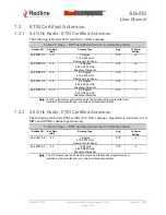
7.4.1 5.4 GHz Radio: FCC & IC Certified Antennas
This device has been designed to operate with the antennas listed below, and having a
maximum gain of 22 dB. Antennas not included in this list or having a gain greater than
22 dB are strictly prohibited for use with this device. The required antenna impedance is
50 ohms.
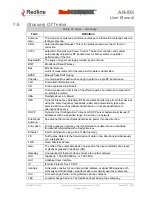
Table 43: Spec. - FCC & IC Certified Antennas: 5.4 GHz Operation
Redline PN
Ant. Gain
(dBi)
Antenna Type
App.
Tx Power
Setting
48-00021-02 22
9
Degree
5.15-5.875 GHz
Directional Flat Panel
PTP -3
Note
: The RF output power and selection must be professionally programmed and
installed by the manufacturer or a trained professional installer.
7.4.2 5.8 GHz Radio: FCC & IC Certified Antennas
This device has been designed to operate with the antennas listed below, and having a
maximum gain of 34.6 dB. Antennas having a gain greater than 34.6 dB are strictly
prohibited for use with this device. The required antenna impedance is 50 ohms. The
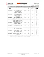
following table lists FCC and IC certified antennas:
Table 44: Spec. - FCC & IC Certified Antennas: 5.8 GHz Operation
Redline PN
Ant.
Gain
(dBi)
Antenna Type
App.
Minimum
Conducted
Power (dBm)
Max
Conducted
Power
Ratings
(dBm)
Average GUI
Power
Display
(dBm)
48-00021-02 22
9
Degree
5.15-5.875 GHz
Directional Flat Panel
PTP -12.7
26.2
20
48-00030-00 22
12
Degree
5.250-5.850 GHz
Directional Parabolic
PTP -12.7
26.2
20
48-00024-00 28
4.5
Degree
5.15-5.875 GHz
Directional Flat Panel
PTP -12.7
26.2
20
48-00031-00 28
6.2
Degree
5.250-5.850 GHz
Directional Parabolic
PTP -12.7
26.2
20
48-00032-00 31.2
4.2
Degree
5.250-5.850 GHz
Directional Parabolic
PTP -12.7
26.2
20
48-00033-00 34.6
3.4
Degree
5.250-5.850 GHz
Directional Parabolic
PTP -12.7
26.2
20
Note
: The RF output power and selection must be professionally programmed and
installed by the manufacturer or a trained professional installer.

