background image

Ellipse 

INSTALLATION GUIDELINES


70-00159-01-09 

Proprietary Redline Communications © 2015


Page 33 of 52 

April 29, 2015 


4.2.3 

Step 3: Restore Default Settings 

When first deploying an Ellipse, it is recommended to perform a factory reset to initialize 
the system parameters. 

Factory Reset 

Web: 

1.  Login to the Ellipse Web interface 

2.  Click 

Configuration->Factory Defaults


Telnet: 

1.  Login to the Ellipse Telnet interface 

2.  Enter the command:  


save defaultconfig 

Long Reset 

If the IP address, username or password of the Ellipse is unknown, use the 'long reset' 
procedure to access the Web or Telnet interface: Refer to the RDL-3000 Family Users 
Guide for a detailed description of this operation. 

4.2.4 

Step 4: Install Options Key 

Options keys (a string of numbers, letters, and dashes) enable Ellipse features including 
the  maximum  uncoded  burst  rate  (UBR)  and  frequency  ranges.  Options  keys  are 
encoded based MAC address, making each key unique to a specific Ellipse. The options 
key enables specific system parameters and must be entered before the Ellipse is put in-
service. 

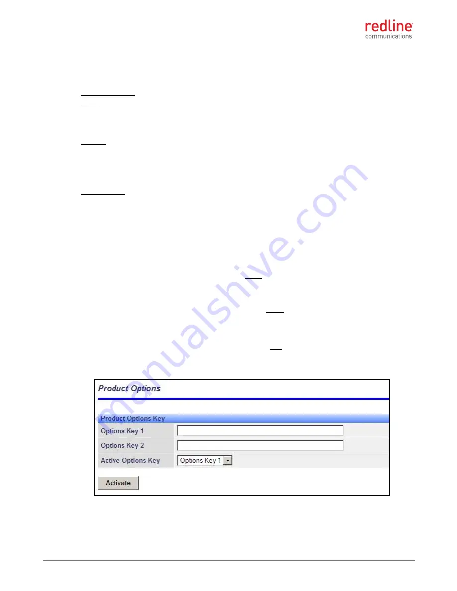
Use the following steps to enter an options key: 

1. 

Use a Web browser to login to the Ellipse. You must login as administrator. 

2. 

Click 

Utilities -> 

Product Options


to display the Product Options screen. 

3. 

Enter a valid permanent or temporary options key in the Options Key 1 field. 

4. 

Click 

Activate

 to enable the new features (does not require reboot). 


Telnet may also be used to install an options key. Refer  to the RDL-3000 Family User 
Manual for a description of the commands. 


Figure 20: Installation: 

Configuration - 

Product Options Screen 


Summary of Contents for RDL-3000 Series

Page 1: ...tary Redline Communications 2015 Pahge 1 of 52 April 29 2015 RDL 3000 Universal Wireless Transport UWT System Ellipse Wireless Sector Controller Installation Guidelines 1 Important Notices 8 2 System Features 14 3 Site Survey 19 4 Installation Procedures 29 5 Reference 45 ...

Page 2: ...Email Inquiries info rdlcom com Support support rdlcom com Training training rdlcom com Document Control 70 00159 01 09 RDL 3000_Ellipse_SC_Installation_Guide 20150429a doc Disclaimer The statements configurations technical data and recommendations in this document are believed to be accurate and reliable but are presented without express or implied warranty Additionally Redline makes no represent...

Page 3: ...a and mounting bracket compatibility matrix 20130904 Remove references to legacy synchronization methods 20130910 Corrected screw sizes on integrated sector antenna mounting brackets 20131002 4 1 7 Add information about the lightweight mounting bracket Change RDL 3000 SC to Ellipse 20131106 3 2 and 4 1 7 All available lightweight mount kits have 400 mm 16 in cables 20131121 Correction to dimension...

Page 4: ...0 Electrical Safety 10 Electrical Safety Compliance Conformité à la Sécurité Electrique 11 UL Information 11 Lightning Protection Protection Contre la Foudre 11 1 4 WEEE Product Return Process 12 1 5 Service Warranty Information 13 2 System Features 14 2 1 System Components 14 2 2 Ellipse Wireless Sector controller 15 RF Ports 15 Ethernet Port 15 2 3 Ethernet Port Weatherproof Gland 16 Ground Lug ...

Page 5: ... 1 2 Step 2 Materials Supplied by Installer 31 4 1 3 Step 3 Review Site Survey 31 4 2 Configure Sector Controller Operating Parameters 32 4 2 1 Step 1 Setup Test Bench 32 4 2 2 Step 2 Login with Test PC 32 4 2 3 Step 3 Restore Default Settings 33 4 2 4 Step 4 Install Options Key 33 4 2 5 Step 5 Required Network and Wireless Settings 34 4 2 6 Step 6 Change Passwords 34 4 3 Install Outdoor Equipment...

Page 6: ...F Planning Fresnel Zone 19 Figure 8 Site Survey Ellipse Antenna Position 21 Figure 9 Site Survey Ellipse Antenna Position 21 Figure 10 Site Survey System Layout Options 22 Figure 11 Site Survey Site Preparation 23 Figure 12 Site Survey System Grounding 24 Figure 13 Site Survey Cabinet Equipment 25 Figure 14 Site Survey Ellipse Lead In Ethernet Cable 26 Figure 15 Site Survey Network Connection Ethe...

Page 7: ... Ethernet Line Protection Device Dimensions Pole Mount 51 LIST OF TABLES Table 1 Notice Electrical Safety Specifications 11 Table 2 Avis Spécifications de sécurité électrique 11 Table 3 Features Redline System Components 14 Table 4 Features Polarization of Wireless Terminal with Integrated Antenna 15 Table 5 Features Ethernet Port RJ 45 Pinout T568B 16 Table 6 Site Survey General Information Setti...

Page 8: ...oceed with an installation without first determining the RF µW exposure risk Where necessary have the relevant transmitters turned off or wear a protective suit for the duration of the installation Safety Warnings Installation of the system must be contracted to a professional installer PoE power adapter caution Warning to Service Personnel 48 VDC Customer equipment including personal computers ro...

Page 9: ...ns the entire equipment installation must comply with the Canadian Electrical Code For installations in the United States the entire equipment installation must be in accordance with Article 810 of the United States National Electrical Code Les appareils RDL 3000 de Redline doivent être installés par un personnel professionnel Le personnel responsable doit s assurer que l installation est bien ach...

Page 10: ...nt must ensure that the antenna is located or pointed such that the antenna does not emit RF fields in excess of the general population limits as defined by FCC CFR 47 Part 2 1091 http www gpo gov fdsys pkg CFR 2009 title47 vol1 pdf CFR 2009 title47 vol1 sec2 1091 pdf FCC OET Bulletin 65 Radio frequency radiation exposure evaluation for fixed devices http transition fcc gov Bureaus Engineering_Tec...

Page 11: ...ection 820 40 of the NEC which provides guidelines for proper grounding and in particular specifies that the cable ground shall be connected to the grounding system of the building as close to the point of cable entry as is practical RDL 3000 system must be installed in compliance with relevant articles in National Electrical Code NEC and equivalent Canadian Code CEC including referenced articles ...

Page 12: ...g and equipment Improperly grounded connections are a source of noise that can cause malfunctions in sensitive equipment The remaining energy on the Ethernet cable shield and conductors can be directed safely to ground by installing a surge arrestor in series with the cable A surge protection system does not prevent lightning strikes but protects equipment by providing a low resistance path for th...

Page 13: ... ii third party products that do not meet Redline s cable and connector assembly specifications or iii cables not installed and weatherproofed as specified in the RDL 3000 Installation Guidelines manual for each product model Refer to the Redline Limited Standard Warranty and RedCare Service agreements WEEE Product Return Process In accordance with the WEEE Waste from Electrical and Electronic Equ...

Page 14: ...em Components Description 1 RDL 3000 Ellipse base station sector controller 2 Flat panel sector antenna wide beamwidth with integrated GPS antenna 3 Line protection LP unit Recommended for lightning protection at cable ingress to building or equipment shed 4 Cat 5e shielded outdoor Ethernet cable terminated with RJ 45 connector each end Connects Ellipse system to PoE and PoE to local area network ...

Page 15: ...g a SISO single antenna or MIMO multiple antenna system RF jumper cables are included with Redline mounting kits When deploying SISO systems in a sector it is important to match the polarization used by the sector controller and subscriber Table 4 Features Polarization of Wireless Terminal with Integrated Antenna RF Port Operating Frequency 2 3 2 8 GHz 3 3 3 8 GHz 4 9 5 8 GHz RF 1 V POL V POL H PO...

Page 16: ... m 30 ft from the PoE to the local network equipment 2 PoE Interoperability Type 2 30 W over two pairs Alternative B Pairs 4 5 7 8 2 3 Ethernet Port Weatherproof Gland A weatherproof gland is provided for the Ellipse Ethernet port The Ellipse Ethernet port must have this gland installed and properly weatherproofed Figure 5 Features Ethernet Port Metal Weatherproof Connector Assembly Ground Lug A g...

Page 17: ... 70 00159 01 09 Proprietary Redline Communications 2015 Page 17 of 52 April 29 2015 Ellipse Dimensions The Ellipse dimensions are 307 x 245 x 60 mm 12 1 x 9 65 x 2 3 in Figure 6 Features Ellipse Wireless Sector controller Dimensions ...

Page 18: ...e the Ellipse Using CLI open a Telnet session to the unit IP address When the command prompt screen appears login to the Ellipse The factory default credentials are username admin password admin The Telnet session is logged out automatically when no commands are received idle for a period of ten minutes Use the following command to exit immediately from the CLI logout ENTER The Ellipse supports tw...

Page 19: ... direct signal path Figure 7 Site Survey RF Planning Fresnel Zone The wireless sector controller also functions under optical line of sight OLOS conditions where a clear straight line path exists between the two end points but the first Fresnel zone is not clear of obstacles If the optical path is completely blocked it may be possible to establish a non line of sight NLOS path using RF signal refl...

Page 20: ...are populated automatically by the DHCP server Table 7 Site Survey Network Syslog Server Settings Setting Radio Management DHCP Enable IP Address Subnet Mask Default Gateway Address Ethernet Mode 3 3 Radio Management Settings The following table contains the minimum set of parameters required to configure the wireless interface Note that these settings are made independently of the Serial Gateway ...

Page 21: ...ill not achieve full operational capability if there is excessive interference on the same or adjacent RF channel Use the built in spectrum sweep feature to determine if a selected RF channel is generally free from interference Figure 8 Site Survey Ellipse Antenna Position IMPORTANT Refer to site survey cell plan for details about collocating multiple sector antennas on a tower mast Recommended an...

Page 22: ...nted on the same mast with an equipment panel box or a separate mast The equipment box may also be any weatherproof enclosure including a shelter portable office utility building etc The distance from the in cabinet PoE to the Ellipse sector controller is limited by the 100 m 330 ft restriction for the total length of the Ethernet cable Figure 10 Site Survey System Layout Options ...

Page 23: ...nstallation of the Ellipse wireless system The following diagram illustrates the main features of a Ellipse installation Figure 11 Site Survey Site Preparation Important Diagram is for informational purposes only Installer may adjust for company standards and Industry Best Practices in effect at site location Both AC and DC power options are available for the Ellipse system ...

Page 24: ...llaneous site metalwork shall be bonded to the earth In addition the following areas must be considered in the overall grounding system for the site All ground rods are to be driven a min of 150 mm 0 5 ft below grade All bends in ground wire to be well rounded curves free of kinks twists etc Resistance to earth as per the best practices An air sector controller lightning rod is to be installed at ...

Page 25: ...ronmental Conditions Cabinet Shelter The equipment cabinet must protect the in cabinet equipment Figure 13 Site Survey Cabinet Equipment Table 10 Site Survey Operating Temperature Range Ellipse Ellipse ER Outdoor 40 to 75 C 40 to 167 F PoE In cabinet 40 to 75 C 40 to 167 F Surge Suppression In cabinet 40 to 85 C 40 to 185 F ...

Page 26: ...ength may affect system performance Surge Suppression The Ellipse wireless sector controller features built in surge suppression on the Ethernet port The system installer must install the surge lightning protection at the Ethernet cable ingress to the equipment cabinet Weatherproofing The importance of proper weatherproofing can not be overstressed The installer must provide weatherproofing materi...

Page 27: ...ction adequate for installations where the cable run and network equipment is within the cabinet or protected by conduit The installer must install additional outdoor rated surge protection at the ingress to the cabinet if the network connection cable routing includes any exposed outdoors areas susceptible to induced voltages from lightning strikes Weatherproofing The importance of proper weatherp...

Page 28: ...r must provide pluggable sector controller blocks in the cabinet to isolate the PoE for installation and servicing Surge Suppression Surge suppression must be provided if the power source is external from the cabinet e g built in to sector controller blocks System installation must include dedicated outdoor rated surge protection for the power cable ingress into the shelter or cabinet Power Requir...

Page 29: ...4 1 Preparation 1 System installation overview 2 Materials supplied by installer 3 Site Survey 4 2 Configure System Operating Parameters 1 Setup test bench 2 Login with test PC 3 Restore default settings 4 Install Options Key s 5 Required Network and RF settings 6 Change Passwords 4 3 Install Outdoor Equipment 1 Attach sector controller to antenna 2 Connect Ethernet and antenna cables RF GPS 3 Ass...

Page 30: ... of 52 April 29 2015 4 1 Preparation 4 1 1 Step 1 System Installation Overview The following diagram illustrates a completed Ellipse installation Review this diagram to become familiar with all requirements for a successful installation Figure 17 Installation Ellipse System Installation Example ...

Page 31: ...quately grounded 3 Antenna Mast The antenna mast must be rated for weight and wind loading of the Ellipse sector controller The mast must be adequately grounded 4 Ethernet Jumper Cable A short CAT 5e RJ 45 jumper cable is required to connect from the PoE to the surge arrestor device at the ingress point of the cabinet Typical length 610 mm 2 ft 5 Power The installer must provide 10 60 VDC or 120 2...

Page 32: ...ser e g Internet Explorer 6 0 or higher The following procedures require a PC equipped with a Web browser Ethernet port and an Ethernet Cat 5e crossover cable for connecting the PC to the PoE power adapter The test PC and Ellipse IP address must be on the same subnet For example IP address 192 168 25 5 Net Mask 255 255 255 0 Figure 19 Installation Configuration Login Screen Web Browser Use the fol...

Page 33: ... 4 Install Options Key Options keys a string of numbers letters and dashes enable Ellipse features including the maximum uncoded burst rate UBR and frequency ranges Options keys are encoded based MAC address making each key unique to a specific Ellipse The options key enables specific system parameters and must be entered before the Ellipse is put in service Use the following steps to enter an opt...

Page 34: ...ation Ellipse Parameter Settings Step Screen Parameter Reference Setting Value 1 Utilities Product Options Options Key RF Plan Enable PMP sector controller SS mode RF frequency etc 2 Configuration System Name Net Plan Name for sector controller System IP Address Net Plan IP address for sector controller 3 Configuration System Mode RF Plan PMP sector controller Wireless Channel Width RF Plan All se...

Page 35: ... a passive GPS antenna The GPS Antenna Type must be set to passive See Configuration Wireless settings in the Ellipse Family user manual 4 3 1 Step 1 Attach Sector Controller to Antenna Part 1 Mounting the Ellipse to the Sector Antenna 1 Place the antenna face down on a working surface that will not damage the radome For example on the inside face of the cardboard shipping package 2 Align the Elli...

Page 36: ...s 2015 Page 36 of 52 April 29 2015 3 Place the Ellipse system on the antenna and secure using using the nuts and washers included in the antenna hardware kit 4 Tighten the nuts to a torque rating of 17 N m 12 5 ft lb Figure 22 Installation Mount and Secure Ellipse to Sector Antenna ...

Page 37: ...erproofing the Antenna and Ethernet Cables Connect Ethernet Cable The Redline outdoor Ethernet cable is terminated with a non hooded RJ 45 connector This connects to the metal RJ 45 connector located on the wireless sector controller enclosure When connecting the outdoor Ethernet cable to the wireless sector controller ensure the RJ 45 plug is fully inserted and locked into the socket Test the loc...

Page 38: ... 3 Connect the Ethernet cable connector to the RJ 45 socket Inserting the RJ 45 plug into the socket should produce an audible click from the locking mechanism 4 Position the gasket 1 against the Ethernet port 5 Thread the body 2 onto the Ethernet port The body must be finger tight plus 1 2 turn or approximately 47 N m 35 ft lb 6 Two sizes of split seals 3 are provided to accommodate single and do...

Page 39: ...k towards the Ethernet cable Stretch and wind the tape back along the Ethernet port nut Do not leave any gaps in the coverage It is recommended to apply a minimum of three 3 layers of splicing tape 2 Mold mastic putty tightly around the bulkhead 3 Wrap the entire port assembly with three 3 layers of PVC tape Seal both ends of the assembly with cable ties to prevent unravelling of the PVC tape Do n...

Page 40: ... washers spring washers and plain nuts Tighten the nuts to a torque rating of 17 N m 12 5 ft lb Figure 26 Installation Integrated Sector Antenna Tilt Brackets 3 Attach the main clamp to the slider adjustment bracket upper Insert the M8 setscrew with plain washer from the outside and secure with an M8 Nyloc Hand tighten only 4 When attaching the main clamp to the tilt selection bracket lower Insert...

Page 41: ...tail Table 15 Installation Integrated Sector Antenna Mounting Kit Parts List Description Quantity Description Quantity Main Pole Clamp 2 M8 x 30 Setscrew 4 Auxiliary Pole Clamp 2 M8 Flat Washer 8 Slider Adjustment Bracket 1 M8 Nut Plain 8 Tilt Selection Bracket 1 M8 Spring Washer 4 M10 x 200 Setscrew 4 M6 Nut Plain 6 M10 Flat Washer 4 M6 Flat Washer 6 M10 Nut 8 M6 Spring Washer 6 ...

Page 42: ... pole Install the auxiliary clamps using the M10 200 mm setscrews and secure each with a flat washer and nut 2 Adjust the horizontal aiming as required before tightening the auxiliary brackets Tighten the nuts on the 200 mm setscrews to 17 N m 12 5 ft lbs Add a second nut to each setscrew and tighten the outer nuts to the same rating while securing the inner nuts with a wrench 3 To adjust tilt pos...

Page 43: ...tial to obtain maximum performance from a wireless link Antenna misalignment results in weaker receive signal strength and it may not be possible to establish the wireless link The alignment must be performed in both the azimuth and elevation planes Before installing the equipment obtain accurate antenna pointing azimuth and elevation angles for each installation site This will allow approximate a...

Page 44: ...ine Communications 2015 Page 44 of 52 April 29 2015 4 4 Install In Cabinet Equipment 4 4 1 Step 1 Install PoE Power Injector Refer to the Site Survey section of this manual 4 4 2 Step 2 Install Ethernet Surge Arrestor Refer to the Site Survey section of this manual ...

Page 45: ...TH and PoE and have surge protection circuitry Figure 29 Reference DC DC PoE Features Ethernet Port Connect this port to to the local 10 100Base T network device Data signals are passed transparently between this port and the PoE port PoE Port Connect this port to to the cable leading to the wireless sector controller Ethernet port System installation must include a dedicated surge protection devi...

Page 46: ...Over load or short circuit Non Functional Fast Blink OFF Input voltage out of range or PoE over temperature DC power Connections The DC supply connections are located on the front panel This is a keyed Buchanan 796864 5 or equiv connector accepting 12 to 24 AWG wires Dual isolated floating power supply inputs are provided to accommodate deployments with backup power e g A B battery banks All power...

Page 47: ...k Ground Lug A 10 grounding lug is located on the back panel This is a common ground The ground lug is connected directly to the PoE chassis and the ground pin GND on the input power connector Figure 32 Reference DC DC PoE Ground Lug PoE Dimensions The surge arrestor dimensions h d w are 110 x 34 x 135 mm 4 4 x 1 3 x 5 4 in Figure 33 Reference DC DC PoE Mounting Dimensions ...

Page 48: ...ace 1 Connect the Ethernet outdoor cable from the Ellipse to the OUTPUT DATA POWER port on the PoE power adapter 2 Connect the test PC or network connection to the INPUT DATA port of the PoE power adapter 3 Connect the PoE power adapter to a compatible power source Figure 34 Reference AC DC PoE Indoor Power Module Pinout to Service Personnel 48 VDC Customer equipment including personal computers r...

Page 49: ...Ellipse INSTALLATION GUIDELINES 70 00159 01 09 Proprietary Redline Communications 2015 Page 49 of 52 April 29 2015 Figure 35 Reference AC DC PoE Mounting Dimensions ...

Page 50: ...e Ethernet Line Protection Device Ethernet Port The protection device includes two RJ 45 F connectors The cables may be connected in any orientation The protection device must be properly grounded to protect against power surges and accumulated static electricity Connect the grounding wire to the device screw lug DIN rail clip or mounting flange Surge Arrestor Dimensions The surge arrestor dimensi...

Page 51: ...ELINES 70 00159 01 09 Proprietary Redline Communications 2015 Page 51 of 52 April 29 2015 Figure 38 Reference Ethernet Line Protection Device Pole Mount Figure 39 Reference Ethernet Line Protection Device Dimensions Pole Mount ...

Page 52: ...Virtual Fiber Outdoor Wireless TCP IP Transport 70 00159 01 09 Proprietary Redline Communications 2015 Pahge 52 of 52 April 29 2015 302 Town Centre Markham Ontario Canada L3R 0E8 www rdlcom com ...

Reviews: