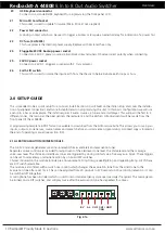
www.altronics.com.au
Redback® Proudly Made In Australia 13
Redback® A 4480B
8 In to 8 Out Audio Switcher
Output levels
Voice Chime Alert
Over
& Evac
24VDC In
(4A M205)
Lift/Chassis
ZONE PLATES OR PRESET PLATE
Keyboard
INPUTS
SW2
SW1
8
7
6
5
4
3
2
1
SW5
ON
OFF
1 Phantom Phantom
Power On Power Off
2
Mic Level Line Level
Switches 3 & 4 Not Used
Vox
Level
Volume
Priority Input
L
R
Vox
Level
Trigger
To Paging Consoles/Preset Plate
3
4
1 2 3 4
ALERT - EVACUATION MODULE
1 2 3 4
L
R
SW3
EV
CO
M
CH1/ C
AN
CH2
AL
2
1
3
1 - Shield
2 - Hot
3 - Cold
1 - Shield
2 - Hot
3 - Cold
2
1
3
SW3 Input 1 & 2 XLR
Phantom Power Settings
SW
ON OFF
(1) Input 1
ON OFF
(2) Input 2 ON OFF
Triggers
OUTPUT
S
8
7
6
5
4
3
2
1
EMERGENCY INPUT
DC Fuse
Earth Lift
+
-
24VDC In
Power Fail
+
_
Manufactured in Australia By
Altronic Distributors Pty. Ltd.
www.redbackaudio.com.au
BCD & DIP SWITCH SETTINGS
DIP SWITCH
CHIME CONTACT
4
5
6
7
CH2
CH1/CANCEL
OFF OFF OFF OFF
Pre Announce
Ding Dong
ON OFF OFF OFF
Pre Announce Repeating Bong
OFF ON OFF OFF
Pre Announce Repeating Bing
OFF OFF ON OFF
Pre Announce
CANCEL
OFF OFF OFF ON
Ding Dong
Pre Announce
ON
ON
ON
ON
Ding Dong
Repeating Bong
OFF ON
ON
ON
Ding Dong
Repeating Bing
ON OFF ON
ON
Ding Dong
CANCEL
ON
ON OFF ON
Repeating Bong Pre Announce
ON
ON
ON OFF Repeating Bong
Ding Dong
OFF OFF ON
ON
Repeating Bong Repeating Bing
OFF ON OFF ON
Repeating Bong
CANCEL
OFF ON
ON OFF
Repeating Bing Pre Announce
ON
ON OFF OFF
Repeating Bing
Ding Dong
ON OFF ON OFF
Repeating Bing Repeating Bong
ON OFF OFF ON
Repeating Bing
CANCEL
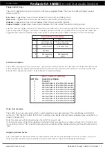
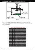
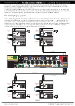
The Alert/Evacuation module has multiple chime options, a recordable
voice-over message and adjustable alert to evacuation tone switch-over times.
These options are selectable inside the unit, via the BCD rotary switch and
DIP switches located on the alert/evacuation module (refer to below settings).
ON
OFF
Momentary Alert
& Evac operation
Latched Alert
& Evac operation
1
2
3
4
Voice-over
message ON
Voice-over
message OFF
Not Used
Not Used
Mic recording
enabled
Mic recording
disabled
DIP
SW
1 2 3 4
SW5
1
2
(Maximum 500mA per output)
8
7
6
5
4
3
1
SW4
(Not Used)
16GB
Maximum
Micro SD Card
2
1 2
3
4
1 2
3
4
1 2
3
4
1 2
3
4
1 2
3
4
Aux Input Sensitivity
DIP Switch Settings
SW1
ON OFF
(1) Input 1 0.3V 0.7V
(2) Input 2 0.3V 0.7V
(3) Input 3 0.3V 0.7V
(4) Input 4 0.3V 0.7V
SW2
ON OFF
(1) Input 5 0.3V 0.7V
(2) Input 6 0.3V 0.7V
(3) Input 7 0.3V 0.7V
(4) Input 8 0.3V 0.7V
2
1
3
2
1
3
2
1
3
2
1
3
2
1
3
2
1
3
2
1
3
2
1
3
2
1
3
2
1
3
2
1
3
FM
101.
10:30 PM
REDBACK
DVD
REDBACK
Audio
Analog Out
L
R
Audio
Analog Out
L
R
Setup Guide
1 - Shield
2 - Hot
3 - Cold
2
1
3
OUTPUT
S
8
7
6
5
4
3
2
1
Output
Voice Chime Alert
Over
& Evac
Optional
Settings
SW4
(Not Used)
1 2 3 4
ZONE PLATES OR PRESET PLATES
INPUTS
SW1
SW2
8
7
6
5
4
3
2
1
Expansion IN Expansion OUT
SW5
ON
OFF
1 Phantom Phantom
Power On Power Off
2
Mic Level Line Level
Switches 3 & 4 Not Used
Vox
Level
Volume
Priority Input
L
R
Vox
Level
Trigger
Paging Consoles / Preset Plates
2
1
1 2 3 4
Input 1 & 2 XLR
Aux Input Sensitivity
DIP Switch Settings
SW1
ON OFF
(1) Input 1 0.3V 0.7V
(2) Input 2 0.3V 0.7V
(3) Input 3 0.3V 0.7V
(4) Input 4 0.3V 0.7V
SW2
ON OFF
(1) Input 5 0.3V 0.7V
(2) Input 6 0.3V 0.7V
(3) Input 7 0.3V 0.7V
(4) Input 8 0.3V 0.7V
ALERT - EVACUATION MODULE
1 2 3 4
L
R
SW3
EVA
C
CO
M
CAN
CHIME
ALER
T
SW
ON OFF
Phantom Power
(1) Input 1
ON OFF
(2) Input 2 ON OFF
(3) Not Used
(4)
Not Used
2
1
3
1 - Shield
2 - Hot
3 - Cold
1 - Shield
2 - Hot
3 - Cold
2
1
3
Dip Switch 3 Settings
Triggers
Levels
OUTPUT
S
8
7
6
5
4
3
2
1
EMERGENCY INPUT
8
6
4
7
5
3
2
1
SW5
24VDC In
(4A M205)
Lift/Chassis
Keyboard
DC Fuse
Earth Lift 24VDC In
Fault Out
+
_
+
-
2
1
3
2
1
3
ON
1 2 3 4
ON
1 2 3 4
ON
1 2 3 4
ON
1 2 3 4
ON
1 2 3 4
2
1
3
2
1
3
2
1
3
2
1
3
2
1
3
2
1
3
2
1
3
2
1
3
2
1
3
Manufactured in Australia By
Altronic Distributors Pty. Ltd.
www.altronics.com.au
2
1
3
2
1
3
2
1
3
2
1
3
2
1
3
2
1
3
2
1
3
2
1
3
POWER
REDBACK
A 4270 125W
Public Address Amplifie
PHASE
5
AMPLIFIER 1
(MAIN BAR)
LINE IN
POWER
REDBACK
A 4270 125W
Public Address Amplifie
PHASE
5
AMPLIFIER 2
(BEER GARDEN)
LINE IN
POWER
REDBACK
A 4270 125W
Public Address Amplifie
PHASE
5
AMPLIFIER 3
(RESTAURANT)
LINE IN
POWER
REDBACK
A 4270 125W
Public Address Amplifie
PHASE
5
AMPLIFIER 4
(KITCHEN)
LINE IN
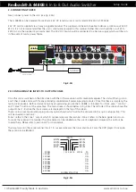
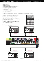
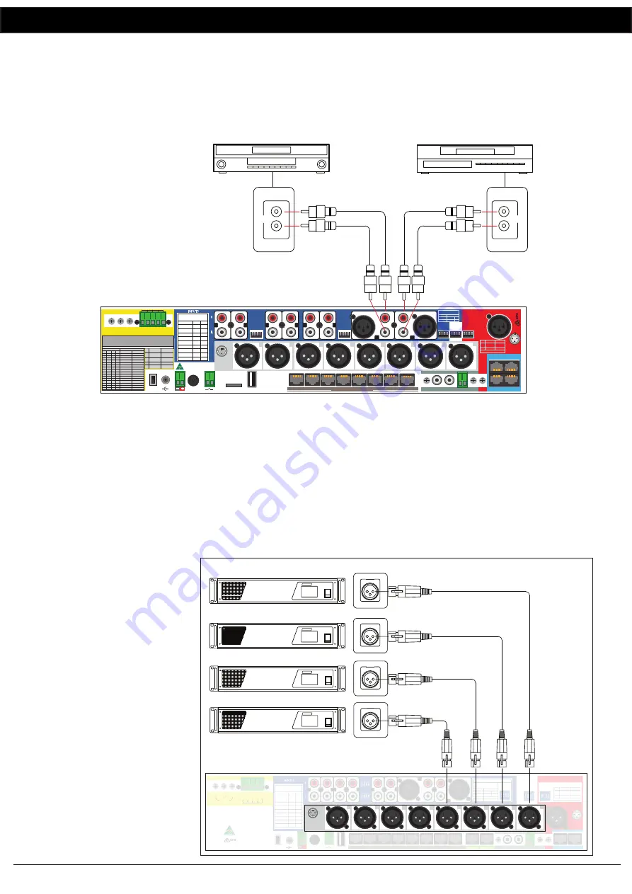
Fig 2.2a
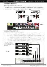
2.2 CONNECTING AUDIO SOURCES
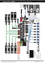
Begin by connecting the audio sources. (see Fig 2.2a).
1 - Use a dual RCA lead to connect the INPUT 1 on the A 4480B to the audio output sockets of the source eg: tuner.
2 - Use a dual RCA lead to connect the INPUT 2 on the A 4480B to the audio output sockets of the source eg: DVD player.
If more audio sources are required, connect them to inputs 3 -8 on the A 4480B.
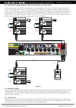
2.3 CONNECTING OUTPUTS
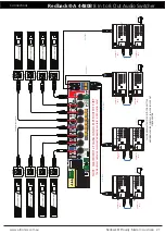
The output sources are next to be connected. (see Fig 2.3A)
1 -
Use a balanced XLR lead to connect OUTPUT 1 on the A 4480B to the line input socket of the zone 1
amplifier. In this example, zone 1 is labelled as “main bar”.
2 -
Use a balanced XLR lead to connect OUTPUT 2 on the A 4480B to the line input socket of the zone 2
amplifier. In this example, zone 1 is labelled as “beer garden”.
3 -
Use a balanced XLR lead to connect OUTPUT 3 on the A 4480B to the line input socket of the zone 3
amplifier. In this example, zone 1 is labelled as “restaurant”.
4 -
Use a balanced XLR lead to connect OUTPUT 4 on the A 4480B to the line input socket of the zone 4
amplifier. In this example, zone 1 is labelled as “kitchen”.
If more output zones are
required, connect them to
outputs 5 to 8 on the rear of
the A 4480B.
Fig 2.3A

