


9
INPUT FREQUENCY CALCULATION
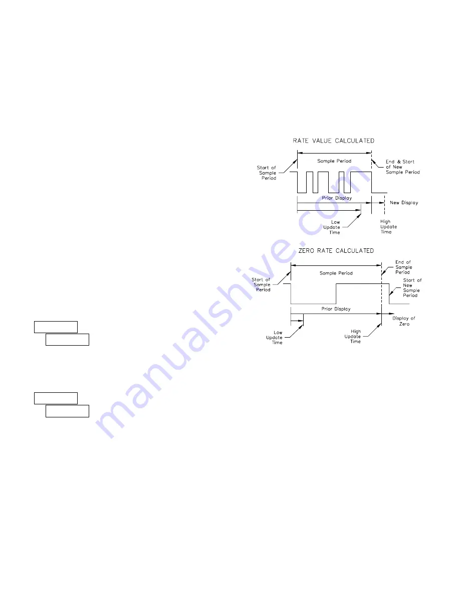
The meter determines the input frequency by summing the number of falling
edges received during a sample period of time. The sample period begins on the
first falling edge. At this falling edge, the meter starts accumulating time
towards Low Update and High Update values. Also, the meter starts
accumulating the number of falling edges. When the time reaches the Low
Update Time value, the meter looks for one more falling edge to end the sample
period. If a falling edge occurs (before the High Update Time value is reached),
the Rate display will update to the new value and the next sample period will
start on the same edge. If the High Update Time value is reached (without
receiving a falling edge after reaching Low Update Time), then the sample
period will end but the Rate display will be forced to zero. The High Update
Time value must be greater than the Low Update Time value. Both values must
be greater than 0.0. The input frequency calculated during the sample period, is
then shown as a Rate value determined by the scaling calculation.
The Low Update Time is the minimum amount of time between display
updates for the rate display. Values of 0.1 and 0.2 seconds will update the
display correctly but may cause the display to appear unsteady.
RATE LOW UPDATE TIME
0.1
to
99.9
seconds
The High Update Time is the maximum amount of time before the rate
display is forced to zero. (For more explanation, refer to Rate Value
Calculation.) The High Update Time
must
be higher than the Low Update Time
and higher than the desired slowest readable speed (one divided by pulses per
second). The factory setting of 2.0, will force the display to zero for speeds
below 0.5 Hz or a pulse every 2 seconds.
RATE HIGH UPDATE TIME
0.2
to
99.9
seconds
"
#
01.0
LO-Udt
"
#
02.0
HI-Udt
SCALING FOR RATE INDICATION
To scale the rate, enter a Scaling Display value with a corresponding Scaling
Input value. These values are internally plotted to a display value of 0 and input
value of 0.0 Hz. A linear relationship is formed between these points to yield a
rate display value that corresponds to the incoming input signal rate. The meter
is capable of showing a rate display value for any linear process.
SCALING CALCULATION
If a display value versus input signal (in pulses per second) is known, then
those values can be entered into Scaling Display (
RAtE dSP
) and Scaling Input
(
RAtE INP
). No further calculations are needed.
If only the number of pulses per ‘single’ unit (i.e. # of pulses per foot) is
known, then it can be entered as the Scaling Input value and the Scaling Display
value will be entered as the following:
NOTES:
1. If # of pulse per unit is less than 10, then multiply both Input and Display
values by 10.
2. If # of pulse per unit is less than 1, then multiply both Input and Display
values by 100.
3. If the Display value is raised or lowered, then Input value must be raised
or lowered by the same proportion (i.e. Display value for per hour is
entered by a third less (1200) then Input value is a third less of # of pulses
per unit). The same is true if the Input value is raised or lowered, then
Display value must be raised or lowered by the same proportion.
4. Both values must be greater than 0.0.
EXAMPLE:
1. With 15.1 pulses per foot, show feet per minute in tenths. Scaling Display
= 60.0 Scaling Input = 15.1.
2. With 0.25 pulses per gallon, show whole gallons per hour. (To have greater
accuracy, multiply both Input and Display values by 10.) Scaling Display
= 36000 Scaling Input = 2.5.
RATE PER
DISPLAY (
RAtE dSP
)
INPUT (
RAtE INP
)
Second
1
# of pulses per unit
Minute
60
# of pulses per unit
Hour
3600
# of pulses per unit


