16
10. Assembly of the Optional DML305/L Extension Support
and DML305/E Bed Extension - cont
Assembly of the DML305/E Bed Extension
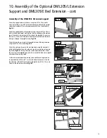
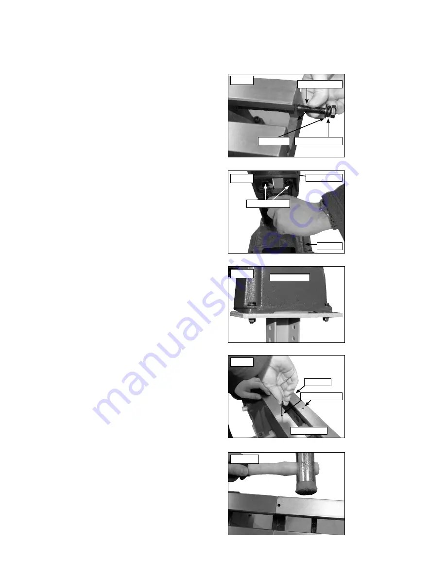
Place an M10 spring washer followed by an M10 washer onto an M10 x
50 mm bolt and screw into the hole on the end of the original bed leaving
approximately 20 mm of the 50 mm M10 bolt exposed,
Fig 10.6
.
Repeat this process for the adjacent hole.
Place the bed extension onto the exposed M10 x 50 mm bolts and tighten
the bolts so that they hold the bed extension in place,
Fig 10.7
. Do not
tighten the bolts fully as some adjustment will be required to make the
bed surfaces flush with one another so that the tailstock runs smoothly
between the original bed and the bed extension.
Attach the foot of the bed extension to the top of the upright plinth using
M8 x 35 mm bolts with M8 washers on either side of the bed extension
and secured with M8 nuts,
Fig 10.8
.
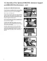
Using the hex wrench supplied, adjust the blind set screws on top of
the optional DML305/L Extension Support bed extension to raise (turn
clockwise) or lower (turn anti-clockwise) the extension until it is flush with
the main bed of the lathe,
Fig.10.9.
Finally, begin to tighten up the M10 x 50 mm bolts to hold the bed
extension as securely as possible making sure that the tailstock runs
smoothly between the original bed and the bed extension. Further
adjustment may be required during this process, this can be done using
a soft mallet without causing damage to the lathe or bed extension,
Fig.10.10
.
Bed extension
Fig.10.8
Fig.10.10
M10 Spring washer
M10 washer
Fig.10.6
50 mm M10 bolt
Bed extension
DML305
Fig.10.7
50 mm M10 bolts
DML305
Bed extension
Fig.10.9
Blind set screws
Summary of Contents for DML305
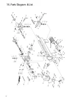
Page 24: ...24 16 Parts Diagram List ...
Page 27: ...27 ...

