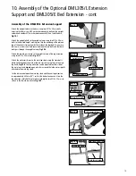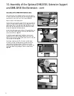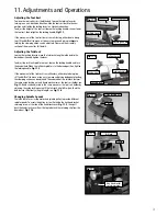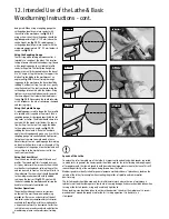
17
Adjusting the Tool Rest
To move the tool rest across the lathe bed, loosen the locking lever by
turning in an anti-clockwise direction, slide the tool rest base to the new
position and tighten the locking lever in a clockwise direction.
To adjust the height of the tool rest loosen the locking handle, raise or lower
the tool rest, then retighten the locking handle,
Fig.11.1
.
If the movement of the tool rest base is unsatisfactory, either due to being
too stiff and difficult to move or too easy to move and giving inadequate
locking, the clamping action can be adjusted. Please see the assembly
section of the manual for full details.
Adjusting the Tailstock
Loosen the locking lever to move the tailstock along the lathe bed to the
desired position and tighten the lever.
To adjust the tailstock spindle in or out, loosen the locking handle and turn
the handwheel. When the tailstock spindle is in the desired position, tighten
the locking handle,
Fig.11.2
.
If the movement of the tailstock is unsatisfactory, either due to being too
stiff and difficult to move or too easy to move and giving inadequate locking,
the clamping action can be adjusted. The underside of the tailstock features
the same nylon locking nut and clamp mechanism as the tool rest holder, see
Fig.
11.3
and can be adjusted in the same manner as the tool rest holder by
adjusting the nylon locking nut until the tailstock is held firmly on the lathe
bed but can slide freely along its length, see
Fig. 11.4
.
Changing Spindle Speeds
The lathe features a six step motor and spindle pulley to provide different
spindle speeds. To access the pulley system first undo the hex head socket
retaining screw at the side of the headstock cover,
Fig. 11.5
, then pull
back the headstock cover from the top to detach the retaining clip from the
domed nut,
Fig. 11.6
.
11. Adjustments and Operations
Locking handle
Fig.11.2
Tailstock arm
Locking lever
Handwheel
Fig.11.4
Tailstock
Clamp
Fig.11.3
Nylon locking nut
Clamp
Fig.11.5
Hex head socket
retaining screw
Fig.11.1
Tool rest
Tool rest holder
Locking lever
Locking handle
Summary of Contents for DML305
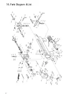
Page 24: ...24 16 Parts Diagram List ...
Page 27: ...27 ...


