background image

7

4. Record Power Guarantee

Products

” means the Products sold by Record Power subject to these 

terms and conditions;

Record Power

” is Record Power Limited, whose company registration 

number is 4804158 and registered office address is Centenary House, 11 
Midland Way, Barlborough Links, Chesterfield, Derbyshire S43 4XA and sells 
through a network of Authorised Dealers;

Authorised Distributor

” is the nominated importer for your region 

who will generally sell through a network of Authorised Dealers.  Details of 
Authorised Distributors for specific countries can be found in the Product 
manual or at www.recordpower.info;

Authorised Dealer

” is a retailer or business authorised to sell Record 

Power Products to end users. 

Guarantee 

1.1

    Record Power guarantees that for a period of 5 years from the date 

of purchase the components of qualifying Products (see clauses 1.2.1 
to 1.2.9) will be free from defects caused by faulty construction  
or manufacture.

1.2

    During this period Record Power, its Authorised Distributor or 

Authorised Dealer will repair or replace free of charge any parts 
which are proved to be faulty in accordance with paragraphs 1.1 
above provided that:

1.2.1

  you follow the claims procedure set out in clause 2 below;

1.2.2

   Record Power, our Authorised Distributor or Authorised Dealer are 

given a reasonable opportunity after receiving notice of the claim to 
examine the Product;

1.2.3

   if asked to do so by Record Power, its Authorised Distributor or 

Authorised Dealer, you return the Product, at your own cost, to 
Record Power’s premises or other approved premises such as those 
of the Authorised Distributor or supplying Authorised Dealer, for the 
examination to take place;

1.2.4

   the fault in question is not caused by industrial use, accidental 

damage, fair wear and tear, wilful damage, neglect, incorrect 
electrical connection, abnormal working conditions, failure to follow 
our instructions, misuse, or alteration or repair of the Product without 
our approval;

1.2.5

   the Product has been used in a domestic environment only;

1.2.6

   the fault does not relate to consumable Products such as blades, 

bearings, drive belts or other wearing parts which can reasonably 
be expected to wear at different rates depending on usage (for full 
details contact Record Power or your local Authorised Distributor);

1.2.7

    the Product has not been used for hire purposes, by you or by a 

previous owner;

1.2.8

   the Product has been purchased by you as the guarantee is not 

transferable from a private sale.  

1.2.9

   where the Product has been purchased from a retailer,  the 5 year 

guarantee is transferable and begins on the date of the first purchase 
of the Product and in the event of a claim under this guarantee proof 
of the original purchase date will be required to validate the  
warranty period.

Claims Procedure

2.1

    In the first instance please contact the Authorised Dealer who 

supplied the Product to you. In our experience many initial problems 
with machines that are thought to be due to faulty parts are actually 
solved by correct setting up or adjustment of the machines. A good 
Authorised Dealer should be able to resolve the majority of these 
issues much more quickly than processing a claim under  
the guarantee.

2.2

    Any damage to the Product resulting in a potential claim under the 

guarantee must be reported to the Authorised Dealer from which it 
was purchased within 48 hours of receipt.

2.3

    If the Authorised Dealer who supplied the Product to you has been 

unable to satisfy your query, any claim made under this Guarantee 
should be made directly to Record Power or its Authorised Distributor 
(for details of the Authorised Distributor in your country please see 
your Product manual or check www.recordpower.info for details). The 
claim itself should be made in a letter setting out the date and place 
of purchase, and giving a brief explanation of the problem which 
has led to the claim. This letter should then be sent with proof of the 
purchase date (preferably a receipt) to Record Power or its Authorised 
Distributor. If you include a phone number or email address this will 
help to speed up your claim.

2.4

   Please note that it is essential that the letter of claim reaches Record 

Power or its Authorised Distributor on the last day of this Guarantee 
at the latest. Late claims will not be considered.

Limitation of Liability 

3.1

    We only supply Products for domestic and private use.  You agree not 

to use the Product for any commercial, business or re-sale purposes 
and we have no liability to you for any loss of profit, loss of business, 
business interruption or loss of business opportunity.

3.2

   This Guarantee does not confer any rights other than those expressly 

set out above and does not cover any claims for consequential loss or 
damage. This Guarantee is offered as an extra benefit and does not 
affect your statutory rights as a consumer.

Notice 


This Guarantee applies to all Products purchased from an Authorised 
Dealer of Record Power within the United Kingdom of Great Britain 
and Northern Ireland. Terms of Guarantee may vary in other countries 
– please check with the Authorised Distributor in your country 
(details of the Authorised Distributor for your country can be found in 
the manual or at www.recordpower.info).

Summary of Contents for DML305

Page 1: ...en using woodworking equipment Always read the instructions provided before using woodworking equipment i Kg Version 3 2 January 2015 To register this product please visit www recordpower info It is important to register your product as soon as possible in order to receive efficient after sales support and be entitled to the full 5 year guarantee Your statutory rights are not affected Please see b...

Page 2: ...e Package 7 Getting to Know Your Lathe 8 Assembly 9 Assembly of the DML305 A Leg Stand 10 Assembly of the Optional DML305 L Extension Support and DML305 E Bed Extension 11 Adjustments and Operations 12 Intended Use of the Lathe Basic Woodturning Instructions 13 Dust Extraction 14 Troubleshooting 15 Electrical Connection Wiring Diagram 16 Parts Diagram List EU Declaration of Conformity ...

Page 3: ... to use the machine Indicates an instruction that requires particular attention Wear protective eyewear Use respiratory protective equipment Use suitable protective footwear Use hearing protection Use protective work gloves Indicates a risk of severe personal injury or damage to the machine Indicates a risk of severe personal injury from electrical shock Risk of personal injury from lifting of hea...

Page 4: ... the machine apply In addition ensure that any vehicles or manual handling equipment used for transportation are of adequate specification 6 The machine should be level and stable at all times When using a leg stand or cabinet base that is designed to be fitted to the machine always ensure that it is securely fastened to the machine using the fixings provided If the machine is suitable to be used ...

Page 5: ...another person as a substitute for a table extension or as additional support for a work piece that is longer or wider than the basic table or to help feed support or pull the work piece Do not attempt to machine more than one work piece at a time When feeding the work piece towards the blade or cutting tool never position your hands in direct line of the cutting path Avoid awkward operations and ...

Page 6: ...e of the Lathe Basic Woodturning Instructions Do not attempt to remount a work piece that has been turned on a faceplate unless you are deliberately turning eccentric work You cannot remount faceplate turned work and expect it to run true as the timber will have expanded or contracted Do not remount a work piece that has been turned between centres if the original centres have been altered or remo...

Page 7: ... been purchased from a retailer the 5 year guarantee is transferable and begins on the date of the first purchase of the Product and in the event of a claim under this guarantee proof of the original purchase date will be required to validate the warranty period 2 Claims Procedure 2 1 In the first instance please contact the Authorised Dealer who supplied the Product to you In our experience many ...

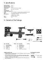
Page 8: ...fications 6 Contents of the Package Max bowl diameter 305 mm Max between centres 393 mm Max swing over bed 305 mm Spindle speeds 350 670 1025 1500 2225 3250 rpm Motor 230 V 50 Hz 1 2 hp 375 W Full load current 2 6 A Tailstock spindle travel 60 mm Thread 3 4 x 16 TPI or M33 x 3 5 mm please refer to machine specification label Taper 1 or 2 Morse Taper please refer to machine specification label Nois...

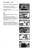
Page 9: ...ition until the machine is completely assembled Installing the Tool Rest Holder to the Lathe Bed To allow the tool rest holder to be attached to the lathe the tailstock must first be removed Remove the hex head screw and retaining washer at the end of the lathe bed to allow the tailstock to be slid from the lathe bed Fig 8 1 On the underside of the tool rest holder is a bolt with a nylon locking n...

Page 10: ...the knockout bar in the circular hole in the spindle nose and hold firmly to ensure the spindle does not turn Now use the spindle wrench on the faceplate collar to loosen the faceplate turning anti clockwise see Fig 8 7 Insert the drive centre into the headstock spindle Fig 8 8 Warning Always disengage the indexing lock before turning the machine on i Drive centre Fig 8 8 Spindle Knockout bar Spin...

Page 11: ...lar hole in the spindle nose and hold firmly to ensure the spindle does not turn Now use the spindle wrench on the faceplate collar to tighten the faceplate turning clockwise see Fig 8 12 Fitting the Revolving Centre to the Tailstock First ensure the locking handle is loosened then insert the revolving centre into the tailstock spindle and tighten the locking handle Fig 8 10 Please note Before ins...

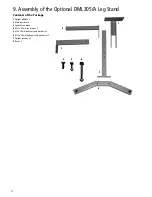
Page 12: ...nd Contents of the Package 1 Upright plinths x 2 2 Male cross brace 3 Female cross brace 4 M10 x 25 mm set screws x 2 5 M8 x 35 mm bolts nuts and washers x 2 6 M10 x 80 mm bolts nuts and washers x 12 7 Upright columns x 2 8 Base x 2 2 3 7 8 1 4 5 6 ...

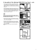
Page 13: ...e note The leg stand is adjustable in height to allow for comfortable use of the lathe As a general rule the centre height of the lathe should be at elbow height 3 Attach the female cross brace to one of the upright columns using two M10 x 80 mm bolts Attach the male cross brace to the remaining upright column in the same manner Fig 9 3 4 To complete assembly of the legstand insert the male cross ...

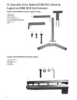
Page 14: ...plinth 2 Male cross brace 3 Female cross brace 4 M10 x 25mm set screws x 2 5 M8 x 35 mm bolts nuts and washers x 2 6 M10 x 80 mm bolts nuts and washers x 6 7 Upright column 8 Base 2 3 7 8 1 4 5 6 Contents of the DML305 E Bed Extension Package 1 M10 x 50 mm bolts x 2 2 M10 washers x 2 3 M10 spring washers x 2 4 Hex wrench 5 Bed extension 5 2 3 4 1 ...

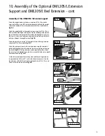
Page 15: ...the upright column of the leg extension using two M10 x 80 mm bolts Fig 10 3 Attach the male cross brace to the main leg stand using the same bolts which hold the either the male or female cross brace in place on the main leg stand Fig 10 4 The Leg extension can be mounted to either side of the main leg stand depending on which way round the lathe was originally attached to the main leg stand Set ...

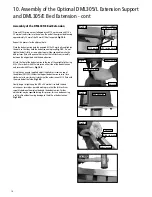
Page 16: ...bed extension to the top of the upright plinth using M8 x 35 mm bolts with M8 washers on either side of the bed extension and secured with M8 nuts Fig 10 8 Using the hex wrench supplied adjust the blind set screws on top of the optional DML305 L Extension Support bed extension to raise turn clockwise or lower turn anti clockwise the extension until it is flush with the main bed of the lathe Fig 10...

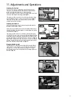
Page 17: ...king handle Fig 11 2 If the movement of the tailstock is unsatisfactory either due to being too stiff and difficult to move or too easy to move and giving inadequate locking the clamping action can be adjusted The underside of the tailstock features the same nylon locking nut and clamp mechanism as the tool rest holder see Fig 11 3 and can be adjusted in the same manner as the tool rest holder by ...

Page 18: ...To turn the lathe on press the green switch marked I on the headstock located beneath the red emergency stop button To stop the machine press the red button marked O on the headstock located beneath the red emergency stop button To stop the machine in an emergency press the large red button located on the headstock Fig 11 7 In the Event of a Blockage or if the Machine Stalls If the lathe stalls du...

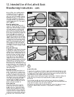
Page 19: ...his will reduce the amount of roughing out needed and also maximise the possible diameter of the final piece 1 Using a square or rectangular profile blank draw two lines one from each opposing diagonal corner to the other at each end of the blank The point where the lines intersect indicates the centre of the blank See fig 12 2 If using irregular shaped timber a centre finder is an invaluable tool...

Page 20: ...e angle of the cutting bevel of the gouge is too shallow and will cause it dig in to the work piece or snatch the tools from your hands Using the Skew Chisel Skew chisels are available in both flat and oval profiles The curved profile is favoured by many as it gives better results more easily Skew chisels are ideal for creating beads refining the profiles and can be used to create a final smooth f...

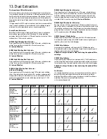
Page 21: ...h motors can be used simul taneously giving maximum suction but in this mode the extractor must be switched off for 20 minutes every hour 0 5 micron filtration DX5000 High Filtration Dust Extractor Bag type extractor 200 litre capacity Twin 1 kW motor suitable for heavy us age ie if one motor is switched off for 20 minutes then the other can be used thus enabling continuous usage Or both motors ca...

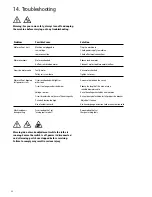
Page 22: ...e or use a suitable diameter cable Voltage too low Have the voltage checked by an electrician Circuit breakers do not have sufficient capacity Have a licensed electrician install proper size breaker Drive belt tension too high Adjust belt tension Use of extension cord Use heavier gauge extension cord or no extension cord Machine labours Excessive depth of cut Decrease depth of cut during cutting T...

Page 23: ...63 plug for use in the UK always ensure that it is fitted with a fuse conforming to BS1362 appropriate to the rating of the machine If replacing the original fuse always fit a fuse of equivalent rating to the original Never fit a fuse of a higher rating than the original Never modify the fuse or fuse holder to accept fuses of a different type or size Where the current rating of the machine exceeds...

Page 24: ...24 16 Parts Diagram List ...

Page 25: ...ey 100 Hex socket set screw M6 x 12 mm 103 Power cable 104 Knockout bar Part No Description 1 Wrench 2 Spur centre 3 Faceplate 4 Spindle shaft 5 Bearing 6005 2Z 6 Ring retaining 47 mm 7 Indexing gear 9 Headstock 10 Washer 47 mm 11 Retaining ring 25 mm 12 Poly v belt 13 Hex socket set screw M6 x 10 mm 14 Spindle pulley 15 Ring retaining 19 mm 16 Handwheel 17 Indexing lock knob 18 Indexing lock tube...

Page 26: ...cing Directives LOW VOLTAGE DIRECTIVE 2006 95EC ELECTROMAGNETIC COMPATIBILITY DIRECTIVE 2004 108EC EN 55014 1 2006 EN 55014 2 1997 A1 2001 A2 2008 EN 61000 3 2 2006 EN 61000 3 3 2008 and conforms to the machinery example for which the EC Type Examination Certificate No SH09081132 001 SH09081132 002 SH09081133 001 at Intertek Testing Services Shanghai Building No 86 1198 Qinzhou Rd North Shanghai 2...

Page 27: ...27 ...
Page 28: ...cordpower co uk Eire Record Power Ltd Centenary House 11 Midland Way Barlborough Links Chesterfield Derbyshire S43 4XA Tel 01246 571 020 Fax 01246 571 030 www recordpower co uk Australia Tools 4 Industry Po Box 3844 Parramatta 2124 Tel 1300 124 422 Fax 1800 262 725 www recordpower com au New Zealand Tools 4 Industry Po Box 276079 Manukau City 2241 Tel 0800 142 326 Fax 09 2717 237 www recordpower c...

Reviews: