background image

6

3. Additional Health & Safety Guidance for 
Woodturning Lathes

Safe Operation
Familiarise yourself with the machine 

•   Machining operations using wood turning lathes have a history of serious 

accidents. Most serious accidents resulted from the work piece being 
thrown from the lathe whilst turning. Other accidents can be caused by 
loose clothing being drawn in to the rotating work piece or hands becom-
ing trapped between the rotating work piece and fixed parts of the lathe.

2. Before switching the machine ‘ON’ 

•   Before attaching a work piece to a faceplate, always prepare it to be as 

round as possible. This will minimise vibration whilst turning. For further 
instructions please see the section of this manual entitled 

Intended Use 

of the Lathe & Basic Woodturning Instructions

.

•   Adjust the tool rest to the correct height and distance from the work 

piece and check that all fixings are secure.

•   Check that the size of the work piece is within the safe working capaci-

ties of the lathe as detailed in the manual.

•   Select the correct speed according to the size and type of work piece.  

The slowest speed is the safest speed to start any new work piece.

•   Always rotate the work piece by hand before starting the lathe to ensure 

it does not come into contact with the tool rest. If the work piece strikes 
the tool rest during operation, it could be split and thrown from  
the lathe.

•   When using a faceplate always ensure the work piece is well secured with 

screws of a suitable diameter and length.

•   Remove any loose knots and bark from the work piece before mounting it 

to the lathe.

•   If mounting a work piece between centres, always ensure that the tail-

stock is correctly adjusted and fully secure. Check that the locking handle 
for the tailstock barrel is fully tightened.

3. Whilst using the lathe 

•   Do not allow the turning tool to dig in to the work piece, which could 

result in the work piece splitting or being thrown from the lathe. Always 
position the tool rest at the correct height. For further instructions please 
see the section of this manual entitled 

Intended Use of the Lathe & 

Basic Woodturning Instructions

•   Before starting to machine a work piece that is off centre or not perfectly 

round, always set the machine to the slowest speed and gradually 
increase speed as the work piece becomes more balanced as material is 
removed. Running the lathe too fast could cause the work piece to be 
thrown from the lathe or the turning tool to be snatched from  
your hands.

•   Always store turning tools in a safe place away from the work area of the 

lathe. Never reach over the rotating work piece to reach for turning tools 
or accessories.

•   Never attempt to adjust the position of the tool rest whilst the machine is 

running. Always switch the machine ‘OFF’ and wait until the work piece 
has stopped rotating before attempting any adjustments.

•   Do not mount a work piece that contains excessive splits or loose knots 

or bark.

•   Keep firm hold and control of the turning tool at all times. Use extreme 

caution when knots and voids are exposed in the work piece. 

•   Finish all hand sanding before removing the work piece from the lathe. 

Do not exceed the speed used for the last cutting operation. For further 
instructions please see the section of this manual entitled 

Intended Use 

of the Lathe & Basic Woodturning Instructions

.

•   Do not attempt to remount a work piece that has been turned on a 

faceplate unless you are deliberately turning eccentric work. You cannot 
remount faceplate turned work and expect it to run true, as the timber 
will have expanded or contracted.

•   Do not remount a work piece that has been turned between centres if the 

original centres have been altered or removed, unless you are deliberately 
turning eccentric work. 

•   If re-mounting any work piece, always set the machine to the slowest 

speed and gradually increase the speed as the work piece becomes more 
balanced as material is removed.

•   Use extra caution when mounting a work piece that has been turned 

between centres to a faceplate, or when mounting a faceplate turning 
between centres, for subsequent machining operations. Always ensure 
that the lathe is set to the slowest speed before switching ON.

•   Do not attempt to perform any machining operations when holding the 

work piece by hand.

•   Do not mount a reamer, milling cutter, wire wheel, buffing wheel, drill bit 

or any other tool to the headstock spindle.

•   Always ensure that the turning tool is in contact with the tool rest and 

fully supported before applying the tool to the work piece.

•   When the tool rest base unit is not in use (e.g. when sanding), it should 

be moved away from the headstock, and the tool rest removed.

4. Maintenance

•   Before attempting any maintenance and particularly when cleaning the 

machine, always remove any accessories and tooling from the machine.

•   Always ensure that any accessories used on the lathe are kept clean and 

free from rust and deposits of resin.

•   Keep all turning tools sharp and in good condition. Check that the 

handles are secure and not split or damaged.

5.

  This machine falls under the scope of the ‘Health & Safety at Work etc. Act 

1974’, and the ‘Provision & Use of Work Equipment Regulations 1998’. 
In addition the elimination or control of risks from wood dust is included 
in the above regulations and the ‘Control of Substances Hazardous to 
Health (COSHH) Regulations 2002’. We recommend that you study and 
follow these regulations. 

     Further guidance is available from The Health & Safety Executive and 

their website www.hse.gov.uk and from the authorised distributor in your 
country (details on back cover of the manual).

2. General Health & Safety Guidance

the machine.

•   A guard or other part that is damaged should be properly repaired 

or replaced by a qualified person unless otherwise indicated in this 
instruction manual. 

•   Do not use the machine if the switch does not turn the machine ‘ON’  

and ‘OFF’.

•  Have defective switches replaced by a qualified person.

31. Warning!


•   The use of any accessory or attachment, other than those recommended in 

this instruction manual, or recommended by our Company may present a 
risk of personal injury or damage to the machine and invalidation of  
the warranty.

32. Have your machine repaired by a qualified person 

•   This machine complies with the relevant safety rules and standards 

appropriate to its type when used in accordance with these instructions 
and with all of the standard safety guards and equipment in place. Only 
qualified persons using original spare parts should carry out repairs. 
Failure to do this may result in considerable danger to the user and 
invalidation of warranty.

33. Caution! Motor may become hot during use

  •  It is normal for motors on some machines to become hot to the touch 

during use. Avoid touching the motor directly when in use.

Summary of Contents for DML305

Page 1: ...en using woodworking equipment Always read the instructions provided before using woodworking equipment i Kg Version 3 2 January 2015 To register this product please visit www recordpower info It is important to register your product as soon as possible in order to receive efficient after sales support and be entitled to the full 5 year guarantee Your statutory rights are not affected Please see b...

Page 2: ...e Package 7 Getting to Know Your Lathe 8 Assembly 9 Assembly of the DML305 A Leg Stand 10 Assembly of the Optional DML305 L Extension Support and DML305 E Bed Extension 11 Adjustments and Operations 12 Intended Use of the Lathe Basic Woodturning Instructions 13 Dust Extraction 14 Troubleshooting 15 Electrical Connection Wiring Diagram 16 Parts Diagram List EU Declaration of Conformity ...

Page 3: ... to use the machine Indicates an instruction that requires particular attention Wear protective eyewear Use respiratory protective equipment Use suitable protective footwear Use hearing protection Use protective work gloves Indicates a risk of severe personal injury or damage to the machine Indicates a risk of severe personal injury from electrical shock Risk of personal injury from lifting of hea...

Page 4: ... the machine apply In addition ensure that any vehicles or manual handling equipment used for transportation are of adequate specification 6 The machine should be level and stable at all times When using a leg stand or cabinet base that is designed to be fitted to the machine always ensure that it is securely fastened to the machine using the fixings provided If the machine is suitable to be used ...

Page 5: ...another person as a substitute for a table extension or as additional support for a work piece that is longer or wider than the basic table or to help feed support or pull the work piece Do not attempt to machine more than one work piece at a time When feeding the work piece towards the blade or cutting tool never position your hands in direct line of the cutting path Avoid awkward operations and ...

Page 6: ...e of the Lathe Basic Woodturning Instructions Do not attempt to remount a work piece that has been turned on a faceplate unless you are deliberately turning eccentric work You cannot remount faceplate turned work and expect it to run true as the timber will have expanded or contracted Do not remount a work piece that has been turned between centres if the original centres have been altered or remo...

Page 7: ... been purchased from a retailer the 5 year guarantee is transferable and begins on the date of the first purchase of the Product and in the event of a claim under this guarantee proof of the original purchase date will be required to validate the warranty period 2 Claims Procedure 2 1 In the first instance please contact the Authorised Dealer who supplied the Product to you In our experience many ...

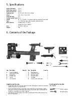
Page 8: ...fications 6 Contents of the Package Max bowl diameter 305 mm Max between centres 393 mm Max swing over bed 305 mm Spindle speeds 350 670 1025 1500 2225 3250 rpm Motor 230 V 50 Hz 1 2 hp 375 W Full load current 2 6 A Tailstock spindle travel 60 mm Thread 3 4 x 16 TPI or M33 x 3 5 mm please refer to machine specification label Taper 1 or 2 Morse Taper please refer to machine specification label Nois...

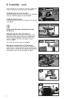
Page 9: ...ition until the machine is completely assembled Installing the Tool Rest Holder to the Lathe Bed To allow the tool rest holder to be attached to the lathe the tailstock must first be removed Remove the hex head screw and retaining washer at the end of the lathe bed to allow the tailstock to be slid from the lathe bed Fig 8 1 On the underside of the tool rest holder is a bolt with a nylon locking n...

Page 10: ...the knockout bar in the circular hole in the spindle nose and hold firmly to ensure the spindle does not turn Now use the spindle wrench on the faceplate collar to loosen the faceplate turning anti clockwise see Fig 8 7 Insert the drive centre into the headstock spindle Fig 8 8 Warning Always disengage the indexing lock before turning the machine on i Drive centre Fig 8 8 Spindle Knockout bar Spin...

Page 11: ...lar hole in the spindle nose and hold firmly to ensure the spindle does not turn Now use the spindle wrench on the faceplate collar to tighten the faceplate turning clockwise see Fig 8 12 Fitting the Revolving Centre to the Tailstock First ensure the locking handle is loosened then insert the revolving centre into the tailstock spindle and tighten the locking handle Fig 8 10 Please note Before ins...

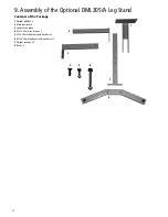
Page 12: ...nd Contents of the Package 1 Upright plinths x 2 2 Male cross brace 3 Female cross brace 4 M10 x 25 mm set screws x 2 5 M8 x 35 mm bolts nuts and washers x 2 6 M10 x 80 mm bolts nuts and washers x 12 7 Upright columns x 2 8 Base x 2 2 3 7 8 1 4 5 6 ...

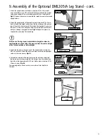
Page 13: ...e note The leg stand is adjustable in height to allow for comfortable use of the lathe As a general rule the centre height of the lathe should be at elbow height 3 Attach the female cross brace to one of the upright columns using two M10 x 80 mm bolts Attach the male cross brace to the remaining upright column in the same manner Fig 9 3 4 To complete assembly of the legstand insert the male cross ...

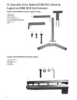
Page 14: ...plinth 2 Male cross brace 3 Female cross brace 4 M10 x 25mm set screws x 2 5 M8 x 35 mm bolts nuts and washers x 2 6 M10 x 80 mm bolts nuts and washers x 6 7 Upright column 8 Base 2 3 7 8 1 4 5 6 Contents of the DML305 E Bed Extension Package 1 M10 x 50 mm bolts x 2 2 M10 washers x 2 3 M10 spring washers x 2 4 Hex wrench 5 Bed extension 5 2 3 4 1 ...

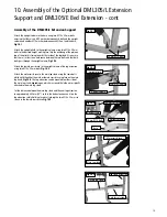
Page 15: ...the upright column of the leg extension using two M10 x 80 mm bolts Fig 10 3 Attach the male cross brace to the main leg stand using the same bolts which hold the either the male or female cross brace in place on the main leg stand Fig 10 4 The Leg extension can be mounted to either side of the main leg stand depending on which way round the lathe was originally attached to the main leg stand Set ...

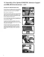
Page 16: ...bed extension to the top of the upright plinth using M8 x 35 mm bolts with M8 washers on either side of the bed extension and secured with M8 nuts Fig 10 8 Using the hex wrench supplied adjust the blind set screws on top of the optional DML305 L Extension Support bed extension to raise turn clockwise or lower turn anti clockwise the extension until it is flush with the main bed of the lathe Fig 10...

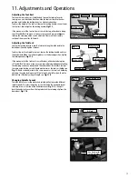
Page 17: ...king handle Fig 11 2 If the movement of the tailstock is unsatisfactory either due to being too stiff and difficult to move or too easy to move and giving inadequate locking the clamping action can be adjusted The underside of the tailstock features the same nylon locking nut and clamp mechanism as the tool rest holder see Fig 11 3 and can be adjusted in the same manner as the tool rest holder by ...

Page 18: ...To turn the lathe on press the green switch marked I on the headstock located beneath the red emergency stop button To stop the machine press the red button marked O on the headstock located beneath the red emergency stop button To stop the machine in an emergency press the large red button located on the headstock Fig 11 7 In the Event of a Blockage or if the Machine Stalls If the lathe stalls du...

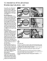
Page 19: ...his will reduce the amount of roughing out needed and also maximise the possible diameter of the final piece 1 Using a square or rectangular profile blank draw two lines one from each opposing diagonal corner to the other at each end of the blank The point where the lines intersect indicates the centre of the blank See fig 12 2 If using irregular shaped timber a centre finder is an invaluable tool...

Page 20: ...e angle of the cutting bevel of the gouge is too shallow and will cause it dig in to the work piece or snatch the tools from your hands Using the Skew Chisel Skew chisels are available in both flat and oval profiles The curved profile is favoured by many as it gives better results more easily Skew chisels are ideal for creating beads refining the profiles and can be used to create a final smooth f...

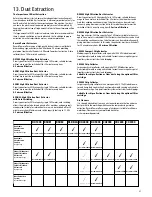
Page 21: ...h motors can be used simul taneously giving maximum suction but in this mode the extractor must be switched off for 20 minutes every hour 0 5 micron filtration DX5000 High Filtration Dust Extractor Bag type extractor 200 litre capacity Twin 1 kW motor suitable for heavy us age ie if one motor is switched off for 20 minutes then the other can be used thus enabling continuous usage Or both motors ca...

Page 22: ...e or use a suitable diameter cable Voltage too low Have the voltage checked by an electrician Circuit breakers do not have sufficient capacity Have a licensed electrician install proper size breaker Drive belt tension too high Adjust belt tension Use of extension cord Use heavier gauge extension cord or no extension cord Machine labours Excessive depth of cut Decrease depth of cut during cutting T...

Page 23: ...63 plug for use in the UK always ensure that it is fitted with a fuse conforming to BS1362 appropriate to the rating of the machine If replacing the original fuse always fit a fuse of equivalent rating to the original Never fit a fuse of a higher rating than the original Never modify the fuse or fuse holder to accept fuses of a different type or size Where the current rating of the machine exceeds...

Page 24: ...24 16 Parts Diagram List ...

Page 25: ...ey 100 Hex socket set screw M6 x 12 mm 103 Power cable 104 Knockout bar Part No Description 1 Wrench 2 Spur centre 3 Faceplate 4 Spindle shaft 5 Bearing 6005 2Z 6 Ring retaining 47 mm 7 Indexing gear 9 Headstock 10 Washer 47 mm 11 Retaining ring 25 mm 12 Poly v belt 13 Hex socket set screw M6 x 10 mm 14 Spindle pulley 15 Ring retaining 19 mm 16 Handwheel 17 Indexing lock knob 18 Indexing lock tube...

Page 26: ...cing Directives LOW VOLTAGE DIRECTIVE 2006 95EC ELECTROMAGNETIC COMPATIBILITY DIRECTIVE 2004 108EC EN 55014 1 2006 EN 55014 2 1997 A1 2001 A2 2008 EN 61000 3 2 2006 EN 61000 3 3 2008 and conforms to the machinery example for which the EC Type Examination Certificate No SH09081132 001 SH09081132 002 SH09081133 001 at Intertek Testing Services Shanghai Building No 86 1198 Qinzhou Rd North Shanghai 2...

Page 27: ...27 ...
Page 28: ...cordpower co uk Eire Record Power Ltd Centenary House 11 Midland Way Barlborough Links Chesterfield Derbyshire S43 4XA Tel 01246 571 020 Fax 01246 571 030 www recordpower co uk Australia Tools 4 Industry Po Box 3844 Parramatta 2124 Tel 1300 124 422 Fax 1800 262 725 www recordpower com au New Zealand Tools 4 Industry Po Box 276079 Manukau City 2241 Tel 0800 142 326 Fax 09 2717 237 www recordpower c...

Reviews:

Related manuals for DML305