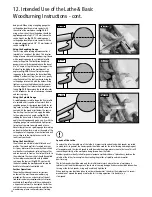
10
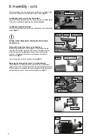
Removing the 4 Prong Drive Centre from the Headstock
The knockout bar is used to remove the drive centre from the headstock
spindle. To do so, insert the knockout bar into the hole positioned centrally in
the hand wheel, at the opposite side of the headstock from the drive centre
and give the drive centre a sharp knock to dislodge it. See
Fig.8.9
.
8. Assembly - cont.
Fig.8.9
Knockout bar
Indexing assembly
Fig.8.6
Installing the Indexing Assembly
Carefully screw the indexing assembly onto the headstock with an adjustable
wrench,
Fig.8.6
.
Fitting the 4 Prong Drive Centre to the Headstock
Before fitting the drive centre, the faceplate must be removed from the
lathe. Place the knockout bar in the circular hole in the spindle nose and
hold firmly to ensure the spindle does not turn. Now use the spindle
wrench on the faceplate collar to loosen the faceplate, turning anti-
clockwise, see
Fig 8.7
.
Insert the drive centre into the headstock spindle,
Fig.8.8
.
Warning: Always disengage the indexing lock before turning
the machine on.
i
Kg
Drive centre
Fig.8.8
Spindle
Knockout bar
Spindle wrench
Fig.8.7
Spindle
Faceplate
Fig.8.4
Tool rest holder
The nylon locking nut can now be tightened until the tool rest holder is held
firmly on the lathe bed but can slide freely along its length,
Fig 8.4
.
Installing the Tool Rest to the Tool Rest Holder
Loosen the locking handle and insert the tool rest into tool rest holder, adjust
the height as required and tighten the locking handle,
Fig.8.5
.
Clamp
Fig.8.5
Tool rest
Tool rest holder
Locking lever
Locking handle
Summary of Contents for DML305
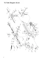
Page 24: ...24 16 Parts Diagram List ...
Page 27: ...27 ...


