REC Peak Energy 72 Installation Manual - UL 1703
Rev C.3 - 02.16
Ref: NE-06-06-C
9
MAINteNANCe
ClEanInG InstRuCtIons
ReC Peak energy 72 panels have been designed for easy maintenance. Normal rainfall will naturally clean the panels if installed at a sufficient
angle. the need for cleaning will vary dependent on location, rainfall, pollution and angle of installation – the lower the angle of installation, the
more cleaning will be required. to optimize electrical output it is recommended to clean the panels when dirt can be seen on the glass surface.
Panel cleaning should be carried out in the early morning when the panels are cool to avoid thermal shock.
If dirt remains on the panel, it may cause cell shading which will reduce power output or even cause further damage. to clean either the
front or rear of the panels, use deionized water at ambient temperature and a sponge, microfiber cloth or a soft brush to wipe away the dirt
(rainwater, tap water or diluted alcohol may also be used as a secondary solution). use a telescopic handle to extend reach. for further
cleaning a mild, biological and biodegradable washing-up liquid may be used.
when cleaning the panel, take care not to scratch the surface or introduce foreign elements that may cause damage. ensure the water used
is free from grit and physical contaminants that may damage the panel. Always rinse the panel with plenty of water. If soiling remains on the
panel, repeat the cleaning process.
Use of high pressure hoses or cleaners is not permitted as these may damage the panels, laminate or cells.
using a rubber squeegee, wipe the panel surface from the top downwards motion to remove any residual water from the panel glass. Panels
can be left to dry in the air or wiped dry with a chamois. Avoid putting pressure on the panel surface when drying.
for more information on cleaning ReC Peak energy 72 solar panels, consult the Cleaning Information sheet available to download from the
online ReC website at www.recgroup.com/download.
systEm InspECtIon
the system should be inspected regularly to ensure that:
•
fasteners are secure, tight and free from corrosion.
•
electrical connections are secure, tight, clean, and free of corrosion.
•
the mechanical integrity of the cables is intact.
•
Bonding points to ground are tight, secure and free from corrosion (which could break the continuity between the panels and ground).
RECyClInG
ReC has made every effort to ensure panel packaging is kept to a minimum. the paper and cardboard packaging can be recycled and
the protective wrapping and panel separating blocks are also recyclable in many areas. Please recycle according to local guidelines and
regulations.
CoNNeCtIoNs AND CoNNeCtoRs
In order to ensure durable and safe connections between panels and Bos equipment, the following instructions must be followed in order
to protect the electrical connections from the elements. More detailed information is given in the guide to Best Practice - Connections and
Connectors which can be found via the ReC website Download Center (www.recgroup.com/downloads).
ConnECtoRs
•
Connectors must be securely joined to each other according to the manufacturer’s instructions. ReC explicitly excludes the cutting of
cables and replacement of connectors. If this causes an issue for a particular site, contact ReC via www.recgroup.com for further advice
•
the use of any chemicals or lubricants on the connectors or contacts must be carried out in line with the connector manufacturer’s
instructions
pRotECtInG tHE CablEs
•
to prevent stress on the junction box casing, ensure the cable exits the junction box in a straight line before any bend in the cable.
•
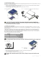
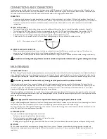
the cables on the ReC Peak energy 72 have a minimum bending radius of 1.2 in (30 mm) to avoid damage to the insulation (fig. 10)
•
ensure cables do not hang loose where they may be damaged through friction or stress, e.g., caused by wind or grazing animals
•
shield connectors from falling or dropping water by locating them directly beneath a panel
•
Cables must be firmly secured to the structure, without overtightening, as this can deform the cable insulation
fig. 10: Minimum bend radius of 1.2 in (30 mm)
sECuRInG CablEs anD ConnECtoRs
•
when securing the connector, place it away from the mounting structure with sufficient air circulation all around. this allows the
connector to dry effectively and avoids the risk of damage or degradation of the connection
•
good practice is to secure the cable either side of the connectors, ensuring no stress is exerted on the connector casing or cable entry
To enable correct cooling and drying of the connectors, do not add extra protection to the connector, e.g., heat shrink, grease or tape
< 60 mm >
< 30 mm >
2.4 in
1.2 in


