REC Peak Energy 72 Installation Manual - UL 1703
Rev C.3 - 02.16
Ref: NE-06-06-C
7
In areas of snow build-up, panels can be subjected to forces in excess of the stated limit even when snow depth does not
appear extreme, causing damage to the framework. If the installation is likely to be affected, further suitable panel support is
recommended, especially on the lower row of panels.
Part Name
Material
Rail
6105 - t5 aluminum extrusion
Bolt
M8 x 25 drop in t-stud kit
Nut
M8 flanged hex nut
When using mounting holes, fixings must be fastened to 16 ft-lbs (21.7 Nm) of torque and installation must be according to fig. 8.
iv) Installation using mounting holes
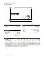
ReC Peak energy 72 panels have been evaluated by uL for mounting using the four elongated holes (18/32 in x 11/32 in (14 x 9 mm)) on
the underside of the panel frame at a distance of 10
7/16
in (270 mm) from the short side edge (fig. 7), utilizing rails and bolts matching the
specifications below.
Installation of ReC Peak energy 72 panels using mounting holes complies with uL 1703 requirements for a maximum design load of 75.2
lbs/ft² (3600 Pa). when installing in this way, the frame and panel edge must be supported by two transverse rails (fig. 1) of aluminium or
galvanized steel (to avoid galvanic corrosion) suitable for the application and appropriate for the local environment. these must be held in
position by bolts and flange nuts according to the specifications below:
observe the following procedures when using mounting holes:
•
Additional electrical bonding to earth is required for the support structure (see section on grounding).
•
All four mounting holes in the frame must be used.
•
fixings must be tightened to 16 ft-lbs (21.7 Nm) using a torque wrench.
The warranty will be voided if additional holes are made in the frame. All fixing and fastening materials should be corrosion
resistant.
fig. 7: Mounting using
mounting holes
GR
GR
GR
GR
47
47
1
1/2
56
1/4
±
1/16
77
1/2
±
1/8
10
7/16
±
1/16
37
13/32
±
1/8
39
±
0.
1
1
3/4
±
3/16
5/8
±
3/16
18/32
11/32
7/
8
1
3/
4
fig. 6: Mounting holes
9
.8
- 13.8”
1”
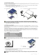
iii) long side mounting using clamps
Mounting utilizing clamps on the two long sides of the panel have been found to be in compliance with uL 1703 requirements for a maximum
design load of 75.2 lbs/ft² (3600 Pa) (fig. 4).
•
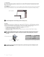
Clamps must be secured between a distance of 9.8 in to 13.8 in (250 mm - 350 mm) from the clamp centerline to the end of the panel.
•
tightening torque must be tightened to 16 ft-lbs (21.7 Nm).
•
the distance between the end clamp and the end of the rail must be minimum 1 in (25 mm).
fig. 4: Long side mounting
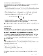
fig. 5:
An array mounting system with each panel secured at four points.


