background image

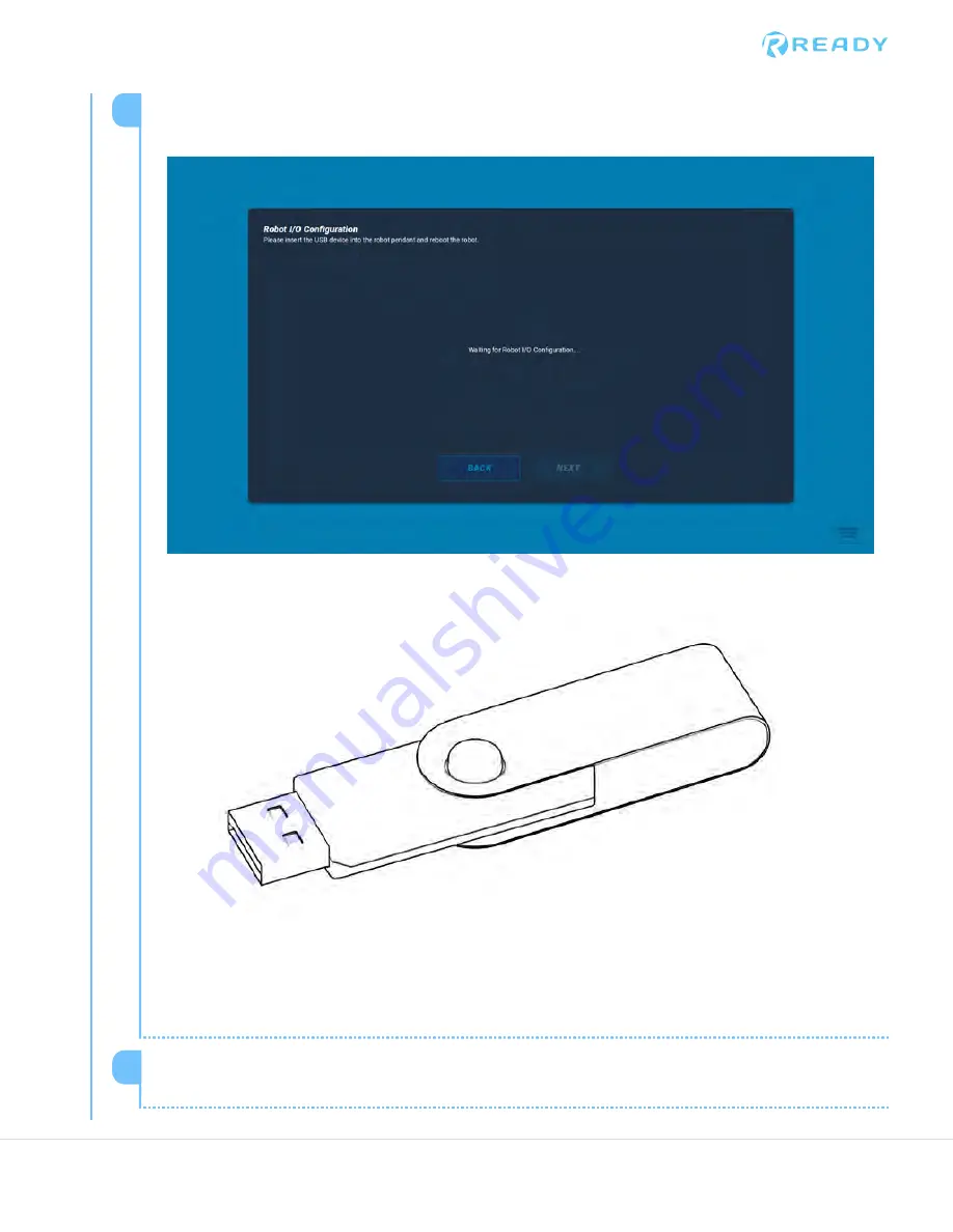
The materials you will need for this step are the UR Teach Pendant and the READY Robotics
Flash Drive that was included with your Forge/Station.

READY Robotics Flash Drive

1

Locate the flash drive and insert it into the USB slot located on the right side of the UR Teach
Pendant.

2

© 2020 COPYRIGHT READY Robotics ALL RIGHTS RESERVED

Summary of Contents for FORGE Station

Page 1: ...General Application Guide...

Page 2: ...page left intentionally blank 2 2020 COPYRIGHT READY Robotics ALL RIGHTS RESERVED...

Page 3: ...are not by themselves a fully integrated workcell As required in ISO 10218 2 READY Robotics strongly recommends performing a complete risk assessment of the integrated workcell per ISO 12100 You may w...

Page 4: ...nents 28 Connecting the Forge Ctrl to power 30 Connecting the Forge Ctrl to air 31 Connecting the READY pendant 33 Startup procedure 34 Turning ON the Forge Ctrl 34 Turning OFF the Forge Ctrl 35 Forge...

Page 5: ...of freedom 66 UR technical specifications 67 Moving the robot arm using Guide Mode 67 Joint limits 68 Moving the robot arm using the Robot Control Panel 70 Jogging your robot 71 Jumping your robot 72...

Page 6: ...Version Version Release Date Change Log 1 1 10 12 2020 Initial Release 6 2020 COPYRIGHT READY Robotics ALL RIGHTS RESERVED...

Page 7: ...open space in front of its door and 4 feet of open space on the side with the trap doors TWO PEOPLE REQUIRED Some of the steps in this uncrating section require two people to safely complete Attemptin...

Page 8: ...or is hinged at the bottom 1 Lift each latch and turn it a full rotation counterclockwise to unlock it Follow the order in the picture in the image from Step 1 Opening the butterfly latch 2 8 2020 COP...

Page 9: ...or of the crate so that it rests on the floor This will act as a ramp for removing your Forge Station 3 Flip down the hinged steel plate at the end of the ramp 4 2020 COPYRIGHT READY Robotics ALL RIGH...

Page 10: ...s Set it aside somewhere where it will not create a trip hazard Do not throw it away as all wood blocks and components of this crate must be sent back to READY 1 Release the ratchet strap by pressing...

Page 11: ...sent back to READY 3 Repeat steps 2 and 3 for the strap on the other side of the Forge Station 4 Carefully pull out the READY pendant from the side of the crate Carefully remove any protective foam or...

Page 12: ...ch on the top right trap door Open the door 8 Remove the wood board that sits on top of the Forge Station s steel tabletop Rotating the board 90 degrees counterclockwise may help you get it out Set it...

Page 13: ...TRIP HAZARD Take caution when placing the wood blocks on the ground as they can create a trip hazard 2020 COPYRIGHT READY Robotics ALL RIGHTS RESERVED...

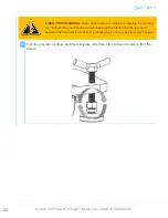
Page 14: ...is a chance of them dragging when the Station is lowered down the ramp Follow the steps below to raise the leveling feet PINCH POINT WARNING Take caution whenever raising or lowering the leveling feet...

Page 15: ...e There is one other leveling foot at the back of the Forge Station but it is already raised 2 With the help of another individual remove your Forge Station from its crate TWO PEOPLE REQUIRED The Forg...

Page 16: ...can train yourself to use the system without causing any collisions The location should also have access to an 80 110 psi air supply and a 120V power supply There are handles on either side of the St...

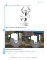
Page 17: ...urning it until one or both of the adjacent wheels are lifted off of the floor 1 Above each foot is a gray jam nut Turn the nut counterclockwise so that it moves up towards the stand Use an adjustable...

Page 18: ...eft storage compartment inside the crate To retrieve them follow these steps Locate the butterfly latch on the underside of the storage compartment 1 Lift the latch and turn it a full rotation counter...

Page 19: ...ution to avoid injury when removing heavy boxes from the compartment 3 Close the door to the storage compartment and secure it shut with the butterfly latch Follow these directions to secure the butte...

Page 20: ...held your stand in the crate back into the crate 2 Neatly place the foam blocks that helped to protect your Forge Station back into the crate 3 Close any trap doors that you opened and secure their re...

Page 21: ...ft the door of the crate and shut the box Make sure that one person is holding the door shut while the other secures the butterfly latches TWO PEOPLE REQUIRED Lifting the crate door and securing its l...

Page 22: ...Secure the butterfly latches in this order 7 22 2020 COPYRIGHT READY Robotics ALL RIGHTS RESERVED...

Page 23: ...hange based on software updates to the Forge OS without notice Overview This section provides information on how to Startup your Forge Station Set up the initial configuration Edit initial configurati...

Page 24: ...ating system designed by READY which runs applications that assist in automating the workcell READY Pendant The Human Machine Interface HMI for Forge OS and Task Canvas Task Canvas The application whi...

Page 25: ...ins and All Outputs Electronic Short Circuit and Overcurrent Protection PLC Inputs Through PLC Breakout Box ONLY Quantity Type 8x Sinking Rated Voltage 24VDC at 4mA nominal Continuous Permissible Volt...

Page 26: ...Push to Connect Fitting Air Output 6mm 4x 6mm Push to Connect Fitting Environmental IP Classification IP 54 Max Operating Temperature 45 degrees C 113 F Min Operating Temperature 0 degrees C 32 F Weig...

Page 27: ...Table Top Dimensions 2020 COPYRIGHT READY Robotics ALL RIGHTS RESERVED...

Page 28: ...ot products Power Disconnect Switch to safely energize and de energize the Forge Ctrl and its peripherals Power Cable NEMA 5 15 Plug to supply power to the Forge Ctrl and its connected peripherals Air...

Page 29: ...he Forge Ctrl Power Button Push Button to turn ON or turn OFF the Forge Ctrl The button lights up to indicate the state of the Forge Ctrl USB 1 USB 2 USB Type A Ports HDMI HDMI Port to connect to the...

Page 30: ...orge Ctrl Element Description LAN 2 Ethernet port to connect the Forge Ctrl to the internet Module 1 2 3 M12 Connectors customizable by READY Connecting the Forge Ctrl to power There is a NEMA 5 15 Po...

Page 31: ...g air from the system will prevent certain peripherals and end effectors from working properly Connecting the Forge Ctrl to air There is a Quick Disconnect Plug on the left side of the Forge Ctrl that...

Page 32: ...ngth 3 16 Plug Tip Diameter 5 16 IMPORTANT Do not disconnect the air supply while the system is on Removing air from the system will prevent certain peripherals and end effectors from working properly...

Page 33: ...EADY Pendant HDMI cable to the port on the Forge Ctrl labeled HDMI 2 Connect the READY Pendant M12 4 Pos Power Cable to the port on the Forge Ctrl labeled 12V Power 3 The connection of the remaining M...

Page 34: ...the robot controller to connect to the Forge Ctrl 2 Connect the robot controller to the Forge Ctrl 3 Setup the Forge Ctrl Initiate Initial Configuration on the READY Pendant 4 Complete remaining robot...

Page 35: ...ge Ctrl On the right side of the Forge Ctrl press the Power Button 2 On the right side of the Forge Ctrl press the Power Button 1 On the READY Pendant select SHUTDOWN 2 2020 COPYRIGHT READY Robotics A...

Page 36: ...wchart that create an executable task for all of the devices you configured in Hardware Configuration The first time you boot up a Forge OS system you will go through the Initial Configuration process...

Page 37: ...tem The Status Bars on the left and right edges of the screen display the current mode of the Forge system The Control Suite across the bottom of the screen gives you access to System Settings and man...

Page 38: ...manual controls for certain devices in robot warning mode and you can still program all block types in TaskCanvas On Universal Robots arm Robot Warning is also triggered by the robot arm s Protective...

Page 39: ...stem is configured Cellular Your Forge Ctrl comes with an internal cellular modem If you do not know your facility s wireless settings and want to connect to a network select CELLULAR Wireless If you...

Page 40: ...ou choose not to create a PIN during initial configuration you can create one at any point later We recommend creating one later rather than right now IMPORTANT If you set up an Admin PIN right now th...

Page 41: ...SAVE PIN The pin is saved in the system IMPORTANT Do not lose or forget the pin that has been created for the Forge Station Otherwise you will have to contact READY to reset it The READY support numb...

Page 42: ...your timezone tap NEXT 3 On the next screen tap YES to indicate that your Forge Station has a force torque sensor All Forge Stations have one If your robot is an e Series UR it will be integrated into...

Page 43: ...If you have a TeachMate tap YES Tap TeachMate V1 or V2 depending on which TeachMate is configured 1 5 2020 COPYRIGHT READY Robotics ALL RIGHTS RESERVED...

Page 44: ...e TeachMate is inline with your end effector and NO if the TeachMate is mounted on the robot arm 2 The last system to configure is the Robot I O Configuration 6 44 2020 COPYRIGHT READY Robotics ALL RI...

Page 45: ...t and the READY Robotics Flash Drive that was included with your Forge Station READY Robotics Flash Drive 1 Locate the flash drive and insert it into the USB slot located on the right side of the UR T...

Page 46: ...il Forge OS says Robot I O Configuration detected Once this is completed the software has configured the Robot I O Tap Next 3 Last step double check your configuration settings Tap COMPLETE SETUP once...

Page 47: ...NETWORK TIME ZONES Troubleshooting guide These lists provide troubleshooting steps for common issues you may experience when starting up the Forge Station If the issue persists contact READY Support T...

Page 48: ...start the Station Turn the Main Power Switch to OFF Wait the green LED to turn off then flip the switch back ON and press the Power Button If the error statement is along the lines of Robot Position V...

Page 49: ...Main Power Switch to OFF and unplug the power source Wait 10 seconds plug the Forge Station back to the power source and flip the Main Power Switch back to ON This typically indicates that the Progra...

Page 50: ...arm so that it does not extend beyond the steel tabletop This will help to ensure that the arm doesn t hit anything during transportation 2 Deactivate Guide mode by pressing the Guide button in the C...

Page 51: ...O boxes unplug them from the Station Typically you should be able to keep your gripper attached unless the gripper protrudes outside the horizontal space of the steel tabletop 8 Take a moment to ensu...

Page 52: ...hands are never between the Station and the jam nut or between the floor and the bottom of a leveling foot These areas form pinch points Turn the gray jam nut above each foot clockwise until it has a...

Page 53: ...ock the wheels of your Forge Station by flipping the plastic tabs on the wheels up 11 Use the handles on your Forge Station to move it 12 Once you have your Forge Station where you want it plug in you...

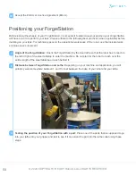
Page 54: ...ion by the door lathe so that the robot has to reach to the left or right of the steel tabletop to enter the machine Do not plan for the robot to reach over the entire length of the steel tabletop or...

Page 55: ...be gripped when it is picked up from its feeder or part s display There is enough clearance on one side of the part so that it can be inserted into the lathe collet without the gripper colliding with...

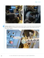
Page 56: ...s of the robot are not too close to any part of the lathe that they might collide with Sometimes the robot may take different paths to reach the lathe collet and it could cause a collision 4 56 2020 C...

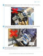
Page 57: ...states Avoid putting your robot into positions where its joints are in alignment This could trigger a warning state in Forge OS See the image below for an example 6 Other relevant destinations Ensure...

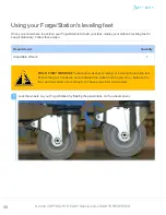
Page 58: ...antity Adjustable Wrench 1 PINCH POINT WARNING Take caution whenever raising or lowering the leveling feet Ensure that your hands are never between the station and the jam nut or between the floor and...

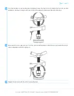
Page 59: ...urning it until one or both of the adjacent wheels are lifted off of the floor 2 Above each foot is a gray jam nut Turn the nut counterclockwise so that it moves up towards the stand Use an adjustable...

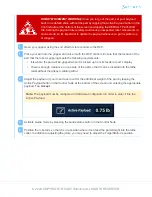
Page 60: ...sition that your task was programmed in all of your waypoints will now be out of alignment If you would like to have a method to realign fix all your waypoints at once this can be accomplished with RE...

Page 61: ...RNING When using a rotary hammer drill or a chemical anchor ensure that the operator is trained and understands the manufacturer s warnings and best practices Mounting procedure Use your marker to rou...

Page 62: ...e steps PINCH POINT WARNING Take caution whenever raising or lowering the leveling feet Ensure that your hands are never between the Station and the jam nut or between the floor and the bottom of a le...

Page 63: ...clearance from the station 1 Turn the handles counterclockwise until it lifts off of the ground 2 Repeat this process for the other two leveling feet 3 With the help of one other person move your Forg...

Page 64: ...mer drill drill each of the four holes to be approximately 4 deep 5 Vacuum or blow any dust out of the mounting hole 6 Move the Station back into alignment with the mounting holes It is helpful to pla...

Page 65: ...ut counterclockwise so that it moves up towards the stand Use an adjustable wrench to tighten it 2 Repeat this process for the other two leveling feet 3 Insert chemical anchor and threaded rod accordi...

Page 66: ...robot at all times as they may form a pinch point while the robot is moving or being moved UR degrees of freedom The UR robot arm has six axes which are labeled in the image below UR Robot arm joints...

Page 67: ...de mode to move the robot s joints and position by hand The easiest way to move your robot arm is to activate Guide mode to move the robot s joints and position by hand These are the terms that you wi...

Page 68: ...r occurs when the emergency stop button is pressed Locate the robot control panel at the bottom of the screen and tap the large State Indicator that says TEACH to activate Guide Mode 1 Move the robot...

Page 69: ...direction Switch the robot out of Guide Mode by tapping the state indicator button labeled GUIDE 7 2020 COPYRIGHT READY Robotics ALL RIGHTS RESERVED...

Page 70: ...uite is located at the bottom of the screen and can be used to access the various functions of the Forge Station and its peripherals Robot Control Panel RCP The Robot Control Panel RCP can be used to...

Page 71: ...esian controls are selected in the panel You may wish to change your reference frame 3 Press and hold one of the directional arrows to move the gripper in the direction corresponding to the same color...

Page 72: ...If you encounter such an error tap FIX from the notification bell and jog the robot out of the pose by using the Joints panel in the RCP In the Jump section of the Robot Control Panel tap JUMP to swi...

Reviews: