Compass
STD 22
Installation and Service manual
Compass STD 22 Compact
45
Edition: Feb, 17, 2006
3646/110--233.DOC010302
To connect the cables to the terminal board, the plastic
cover has to be pulled off from the terminal board.
Cables should not be lengthened too long, to prevent a
short circuit to a neighbour terminal by an inadvertently
loosening.
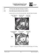
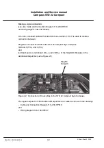
Additionally the cable should be fixed (as shown in
Figure 24) with tie wraps and self adhesive tie mounts.
After that the plastic cover has to be pulled on the ter-
minal board.
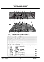
The ship‘s electrical supply ( AC
IN
= 115...230V, 50/60Hz) must be connected to the
terminal board at terminals
17
and
19
or
18
und
20
see Figure 24.
To connect the AC/DC Converter with a 24VDC load, use cables which meet the
following minimum requirements:
-- 2 x 2,5mm
2
(with screen) gyro compass
-- 2 x 0,5mm
2
(with screen) Additional Output Box
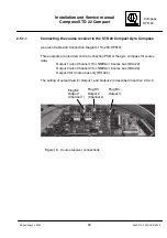
The output voltage (24VDC supply) is taken from the terminals:
6
(24VDC) and
11
(0V) or
7
(24VDC) and
12
(0V) or
8
(24VDC) and
13
(0V) or
9
(24VDC) and
14
(0V) .
Before connecting the 24VDC load to the AC/DC Converter, the output voltage must be
measured. It must be within the tolerance range of 18 VDC to 36 VDC.
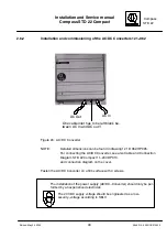
After the ship‘s mains is switched on, the AC/DC Converter is supplied at 24VDC.
The AC/DC Converter does not need to be switched on separately.

