Compass
STD 22
Installation and Service manual
Compass STD 22
91
Edition: May 20, 2005
3646/110--233.DOC010302
3.4.2
Creating a cable connection from STD 22 Compass
→
Distribution Unit
NOTE: The installation and commissioning of the Distribution Unit are described in the
Distribution Unit manual.
To create cable connections to the Distribution Unit, see also Cable and
Connection Diagram 110--233. HP009 or HP029.
This connection is made using cables with CAN bus plugs at both ends
(see also section 3.4.2.2 -- Connecting the CAN bus plug).
For each CAN bus, a screened 2-core twisted cable with a conductor cross-section of
≥
0.5mm
2
must be used.
There is a redundant CAN bus:
-- CAN1 bus
-- CAN2 bus
Each CAN bus must be connected.
Missing or disconnected plug connections will cause an error message to be sent to the
Operator Unit (see manual 3648, Operator Unit 130--613).
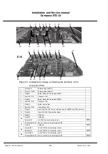
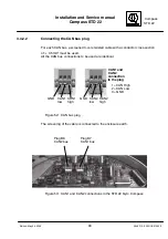
The plugs must be inserted on the Connection PCB as shown in Figure 50.
If several STD 22 gyro compasses are combined with one another, they are connected
to each other from compass to compass via the CAN bus.
For this purpose, each device is equipped with 2 sockets (CAN1 = B7 and CAN2 = B8)
(e.g. CAN1 and CAN 1 OUT), whereby CAN OUT does not have to be connected if the
compass in question is installed virtually as a terminal device.
The compass or compasses can also be connected via any other CAN bus user.
When inserting plugs, be sure not to get
the plugs mixed up.
The CAN1 bus must always be connected
to the CAN1 bus of the subsequent device.
If a compass is operated within a CAN bus
configuration as a terminal device on the
CAN bus, terminating resistors must be
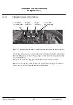
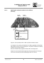
activated for each CAN bus
(see section 3.4.2.3).
The total length of the CAN bus cable must not
exceed a length of 300 m.


