


TEMPERATURE CONTROL
49
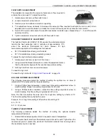
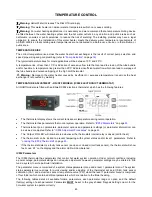
AMBIENT AIR COMPENSATOR
The RWF55 electronic thermostat can be configured to use
weather-compensated set point
shifting.
When weather-compensated set point shifting is selected the set point
is automatically adjusted
according to the outdoor temperature; this function assists in reducing temperature fluctuations
in the building due to additional heat being gained or lost due to the weather. Each Raypak
must have its own outside sensor (no parallel connection).
An LG-Ni1000 or PT1000 outdoor sensor (not supplied) must be connected across terminals
31 & 32 of the RWF55 and the following parameters must be correctly set.
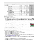
Parameters for Optional Ambient Air Compensator
– RWF55 Electronic Thermostat
The following parameters enable the weather-compensated set point shifting function of the RWF55 electronic
thermostat.
To access and adjust the Configuration (ConF) Level Parameters refer to
"Adjusting Configuration Level
Parameters"
on page
48
.
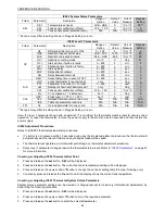
RWF55 Configuration (ConF) Level Parameters
Level
Parameter
Display
Value Range
Raypak Setting
InP InP3
Sensor Type
Sen3
0....3
1 - Pt1000 / 2 - LG-Ni1000
Function
FnC3
0….1
1 - weather compensated set point
Correction of measured value
OFF3
-
1999….+9999
0
– No offset
Filter Time Constant
1
dF3
0.0….1500.0
1278 seconds
1
The filter time constant is used to adapt the digital 2
nd
order input filter (time in s; 0 s = filter off). If the input signal changes abruptly, approx
26% of the change is captured after a time corresponding to the filter time constant dF3 (2 x dF3: approx 59% is captured; 5 x dF3 approx 96%
is captured.
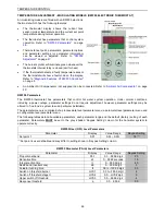
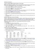
The
following
parameters
determine
the
target
temperature for a particular outdoor temperature and also
set the heating curve slope.
Prior to altering the settings advice should be sought from
the heating system designer to determine the optimum
values suitable for the application.
NOTE: Incorrect setting may cause unacceptable
temperature fluctuations in the heating system.
To access and adjust the Parameter (PArA) Level Parameters refer to
"Checking or Adjusting Parameter (PArA)
Level Parameters"
on page
48.
NOTE: The parameters below cannot be accessed until the Parameter FnC3 has been set, refer to page
49
.
RWF55 Parameter (PArA) Level Parameters
Parameter
Display
Range
Function
Default
Setting
Outside
temperature
Curve point 1
At1
-
40….120
Sets the target heater temperature for an outdoor
temperature and determines point 1 of the heating curve
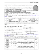
Refer to heating curve slope diagram above
-10
Heater
temperature
Curve point 1
Ht1
SPL….SPH
60
Outside
temperature
Curve point 2
At2
-
40….120
Sets the target heater temperature for an outdoor
temperature and determines point 2 of the heating curve
Refer to heating curve slope diagram above
20
Heater
temperature
Curve point 2
Ht2
SPL….SPH
50
Heating Curve Slope
Summary of Contents for B0507
Page 26: ...CONNECTIONS ELECTRICAL 26 Wiring Diagram for Typical BMS System Interface ...
Page 28: ...CONNECTIONS ELECTRICAL 28 WIRING DIAGRAMS ON OFF MODELS 1000MJ NG ...
Page 29: ...CONNECTIONS ELECTRICAL 29 ON OFF MODELS 1000MJ LPG ...
Page 30: ...CONNECTIONS ELECTRICAL 30 ON OFF MODELS 1000MJ ...
Page 31: ...CONNECTIONS ELECTRICAL 31 MODULATING MODELS 1000MJ NG DRAWING No 96159611B ...
Page 32: ...CONNECTIONS ELECTRICAL 32 MODULATING MODELS 1000MJ LPG DRAWING No 96159610C ...
Page 33: ...CONNECTIONS ELECTRICAL 33 MODULATING MODELS 1000MJ DRAWING No 96159613B ...


