
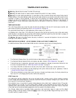


TEMPERATURE CONTROL
47
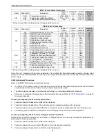
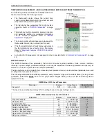
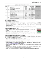
RWF55 Configuration (ConF) Level Parameters
Menu
Sub
Menu
Parameter
Display
Value Range
Raypak Setting
InP
InP1
Sensor Type
SEn1
1….19 digit
6
Correction of measured value
OFF1
-
1999….+9999 digit
0
Start of display
SCL1
-
1999….+9999 digit
0
End of display
SCH1
-
1999….+9999 digit
100
Filter time constant, analog input 1
dF1
0.0…..100.0 digit
1
Temperature unit
Unit
1….2 digit
1
ConF
Cntr
Controller type
CtYP
1….2 digit
1
Operating Action
CACt
0….1 digit
1
Lower set point limit
SPL
-
1999….+9999 digit
0
Upper set point limit
SPH
-
1999….+9999 digit
95
AF
Alarm function
FnCt
0….12 digit
0
Limit value
AL
-
1999….+9999 digit
0
Switching differential
HYSt
0….999.9
1
Response to Out Of Range
ACrA
0….1 digit
0
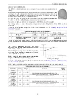
RWF55 Adjustment Procedures
Notes to all RWF55 adjustment procedures:
If a button is not pressed within 180 seconds during any thermostat adjustment procedure, and
‘ENTER’
has not been pressed to save the new value, the thermostat display will revert to show the current probe
temperature without modifying the selected parameter. If this occurs it will be necessary to reprogram the
selected parameter.
The thermostat will operate as normal whilst performing any thermostat adjustment procedure.
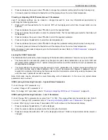
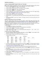
Checking or Adjusting RWF55 Set Point
1.
Press and release the
(▼) button, the current set point temp (green display) will start
flashing.
2.
Press and release
(▲) or (▼) to adjust the set point to the required value.
3.
Press and release
‘ENTER’
to confirm the new setting. The green display will stop flashing
and the new set point will be displayed.
Checking or Adjusting RWF55
‘User (OPr)
Level’ Parameters
Note: For Raypak standard programming only user level parameter SP 1 is able to be adjusted, other parameters
may be available but are display only at this level.
1.
Press and release
‘ENTER’, ‘
OPr
‟ appears in the lower display.
2.
Press and release
‘ENTER’; ‘
SP 1
‟ and the current set point are displayed.
3.
Press and release
‘ENTER’; ‘
SP 1
‟ will start flashing
4.
Press and release (▲) or (▼) button to enter the value for SP 1 as shown in the „Raypak Setting‟ column of
the
"RWF 55 User Level Parameters"
table on page
46
.
5.
Press and release
‘ENTER’
to accept the new setting.
„SP 1‟ will cease flashing and the new set point will be
displayed.
6.
Press and release (▲) or (▼) button, „InP1‟ and the current water temperature will be displayed. This is
information only to confirm the sensor is reading the correct water temperature.
7.
Press
‘ESC’
for
more than 2 seconds, the display will revert to show the probe and set point temperatures.
Summary of Contents for B0507
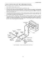
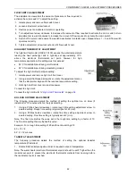
Page 26: ...CONNECTIONS ELECTRICAL 26 Wiring Diagram for Typical BMS System Interface ...
Page 28: ...CONNECTIONS ELECTRICAL 28 WIRING DIAGRAMS ON OFF MODELS 1000MJ NG ...
Page 29: ...CONNECTIONS ELECTRICAL 29 ON OFF MODELS 1000MJ LPG ...
Page 30: ...CONNECTIONS ELECTRICAL 30 ON OFF MODELS 1000MJ ...
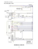
Page 31: ...CONNECTIONS ELECTRICAL 31 MODULATING MODELS 1000MJ NG DRAWING No 96159611B ...
Page 32: ...CONNECTIONS ELECTRICAL 32 MODULATING MODELS 1000MJ LPG DRAWING No 96159610C ...
Page 33: ...CONNECTIONS ELECTRICAL 33 MODULATING MODELS 1000MJ DRAWING No 96159613B ...


