


CONNECTIONS
– PLUMBING
18
MINIMUM PRESSURE REQUIREMENTS FOR GRUNDFOS UPS SERIES PUMPS
Pump
Models
Minimum Inlet Head Required at Operating
Temperature (m)
75
°
C
80
°
C
85
°
C
90
°
C
95
°
C
UPS32-80N
507,538,658,768,868
0.5
0.5
0.5
3.0
5.0
UPS40-60/2B
768,868,972,992,1142,1182,1242,1292
1.5
2.5
3.5
4.5
7.0
UPS50-120FB
1362,1412,1662,1722,1852,1922,2004,2214
4.0
5.0
6.0
7.0
9.0
UPS80-120FB
2404,2634,2804,3164,3304,3694,3804,4224
16.0
17.0
18.0
19.0
20.5
WATER HEATING
Where the water heater is supplied as part of a package, including the storage cylinder and pump, the installation
must comply with the drawing provided. Failure to observe this requirement may result in ineffective hot water
capacity or damage.
GAS INLET
The pipe work must be cleared of foreign matter before connection and purged at the union to the gas control or
pressure regulator before attempting to light the water heater. If this procedure is not performed, a flame failure
lockout may result on initial start up.
An isolation valve and disconnection union must be installed to allow servicing and removal of the water heater.
Refer to AS/NZS 5601 or AS/NZS 5601.1 for the correct pipe sizing.
Warning:
Before pressure testing the gas supply system always isolate and disconnect the water heater after
the isolating cock to prevent the risk of serious damage to the gas control or pressure regulator. Warranty does not
cover damage of any nature resulting from failure to observe this precaution. Refer to the water heaters rating label
for gas types and pressures.
The heater and its gas connection must be thoroughly leak tested before placing in operation. Use soapy water and
a manometer to test for gas leaks.
DANGER!
Do not use an open flame to check for gas leaks.
CAUTION:
Care is necessary when tightening fittings into the gas control or pressure regulator. The gas control or
pressure regulator casting may crack if the fittings are over tightened. Cracked castings are not covered under
warranty. Damaged gas controls and pressure regulators must be replaced.
COLD WATER SUPPLY / MAKEUP
All pipe work must be cleared of foreign matter before connection and purged before attempting to operate the
water heater. All olive compression fittings must use brass or copper olives. Use thread sealing tape or an
approved thread sealant on all other fittings.
Mechanical, Hydronic and Process Heating Applications
The pressure of the makeup supply must be controlled. This may be achieved by the use of a pressure limiting
valve or a header tank which is designed to provide the correct operating pressure for the system.
Where the water heater is fitted with a 60 PSI relief valve, the maximum supply pressure setting must not exceed
330 kPa. The minimum inlet pressure is dependent on a number of factors including operating temperature,
minimum inlet pressure for circulating pumps and system pressure losses.
Backflow prevention in accordance with AS/NZS 3500.1 may be required, please check with the local water supply
authority for any local code requirements.
A suitably sized expansion vessel must be fitted to a closed heating system to prevent discharge of system fluid
during the heating cycle.
Domestic Hot Water Applications
An isolation valve and non return valve must be installed on the cold water line to the system. An acceptable
arrangement is shown in the
“Cold Water Connection Plumbing Diagram”
on page
15
.
The cold water supply to a domestic water heating system must be fitted with a pressure limiting valve if the water
supply pressure exceeds 80 % of the lowest rated relief valve in the system.
The cold water supply pressure must be sufficient to provide adequate flow at the fixtures.
Summary of Contents for B0507
Page 26: ...CONNECTIONS ELECTRICAL 26 Wiring Diagram for Typical BMS System Interface ...
Page 28: ...CONNECTIONS ELECTRICAL 28 WIRING DIAGRAMS ON OFF MODELS 1000MJ NG ...
Page 29: ...CONNECTIONS ELECTRICAL 29 ON OFF MODELS 1000MJ LPG ...
Page 30: ...CONNECTIONS ELECTRICAL 30 ON OFF MODELS 1000MJ ...
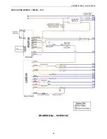
Page 31: ...CONNECTIONS ELECTRICAL 31 MODULATING MODELS 1000MJ NG DRAWING No 96159611B ...
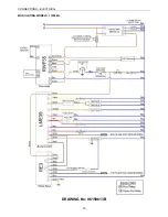
Page 32: ...CONNECTIONS ELECTRICAL 32 MODULATING MODELS 1000MJ LPG DRAWING No 96159610C ...
Page 33: ...CONNECTIONS ELECTRICAL 33 MODULATING MODELS 1000MJ DRAWING No 96159613B ...


