


CONNECTIONS
– ELECTRICAL
25
Warning: THE WATER HEATER MUST NOT OPERATE WITHOUT THE CIRCULATING PUMP RUNNING.
ELECTRONIC THERMOSTAT TEMPERATURE SETTING (SET POINT)
For reasons of safety and economy, we recommend that the electronic thermostat set point is set at the lowest
temperature that will provide sufficient hot water. Discuss the temperature setting requirements with the
householder or responsible officer. Refer to
“Temperature Control”
on page
43
.
INTERMITTENT PUMP OPERATION
For applications utilising intermittent pump operation, a run on timer is provided (modulating models only). For
on/off models, an optional pump run on timer kit part number 56076874 must be fitted to the water heater to
prevent nuisance tripping of the high limit thermostat due to residual heat build up in the heat exchanger. The timer
should be set to allow the pump to operate (run on) for at least ten (10) minutes.
EXTERNAL CONTROLS
Modulating models can be wired for use
with an external control such as a remote
thermostat or a remote time switch. To
connect an external control to the water
heater it is necessary to remove the
bridging wire between terminals marked
“TO
TANKSTAT
”
and
“FROM
TANKSTAT
” and connect the external
control across these two terminals (refer
to the diagram opposite and to the wiring
diagrams on pages
28
to
33
.
On/Off models may be wired as depicted above with the installation of kit 56076874 (supplied separately).
Where a remote thermostat such as a tankstat is utilised, the water heaters electronic thermostat set point should
be adjusted to 5º higher than the setting on the remote thermostat (Refer to
"Temperature Control"
on page
43
.
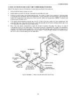
POWER FLUEING
If the flue cannot be designed as outlined in the
„Indoor Installation‟
section on page
12
, then a power flue may be
required. Power flues must be designed by persons competent to do so and must be electrically interlocked with
the water heater(s). Contact Raypak for power flue wiring diagrams.
FLOW SWITCH
A flow switch is provided with the water heater and is wired to prevent operation of the main burner in the event of
no water flow. Refer to
“Flow Switch Adjustment” on page
42
.
Warning: THE WATER HEATER MUST NOT OPERATE WITHOUT THE CIRCULATING PUMP RUNNING.
BUILDING MANAGEMENT SYSTEM (BMS)
For applications requiring connection to a building management system, relays are installed as standard on all
models
to provide „run‟ and „fail‟ status indication. The diagram on page
26
details a typical BMS system interface.
AMBIENT AIR COMPENSATOR
An Ambient Air Compensator (not supplied) may be installed and connected to the RWF55 electronic thermostat
on modulating models (refer to
“Ambient Air Compensator”
on page
49
).
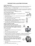
CONTROL PANEL ACCESS
To access the electrical enclosure:
Remove the 3 Hex head screws from the clear Perspex front panel.
Remove the front panel.
Summary of Contents for B0507
Page 26: ...CONNECTIONS ELECTRICAL 26 Wiring Diagram for Typical BMS System Interface ...
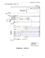
Page 28: ...CONNECTIONS ELECTRICAL 28 WIRING DIAGRAMS ON OFF MODELS 1000MJ NG ...
Page 29: ...CONNECTIONS ELECTRICAL 29 ON OFF MODELS 1000MJ LPG ...
Page 30: ...CONNECTIONS ELECTRICAL 30 ON OFF MODELS 1000MJ ...
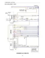
Page 31: ...CONNECTIONS ELECTRICAL 31 MODULATING MODELS 1000MJ NG DRAWING No 96159611B ...
Page 32: ...CONNECTIONS ELECTRICAL 32 MODULATING MODELS 1000MJ LPG DRAWING No 96159610C ...
Page 33: ...CONNECTIONS ELECTRICAL 33 MODULATING MODELS 1000MJ DRAWING No 96159613B ...


