background image

8. To save all changes, select the Save button located at the top of the page.

Manual APN settings configuration

When you power up the router after inserting a SIM card the APN settings
may be configured automatically. How ever if you

Correct APN settings for your SIM provider can be found by searching the
internet for <provider name> APN settings e.g.: Giff Gaff APN settings.
There may be different settings for monthly contract SIMs and pay as you
go (PAYG) SIMs.

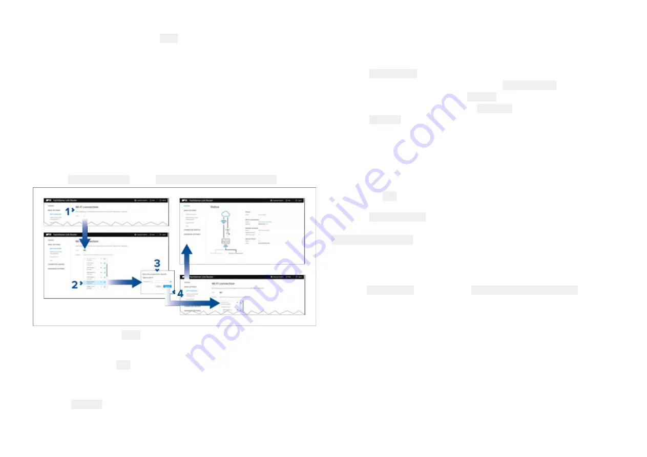
Connecting to an available Wi-Fi network

Follow the steps below to connect to an external Wi-Fi network (e.g.: the
Wi-Fi hotspot at your marina).

From the Wi-Fi connection page: Basic settings > Wi-Fi connection.

1. Enable your router’s Wi-Fi connection using the toggle switch.
2. Select the Wi-Fi network you want to connect to from the list.

You can select the Info icon next to the Wi-Fi network to view information
about the network.

3. Enter the password for the network in the password field.
4. Select Connect.

Connecting to a Wi-Fi network manually

You can connect to a network that is not in the list but is in range, i.e.: a Wi-Fi
network that is not broadcasting its SSID.
1. Select Add network.
2. Enter the Wi-Fi network name (SSID) in the Network name field.
3. Select the Security type from the Security drop down box.
4. Enter the networks password in the Password field.
5. Select Connect.

Forgetting a saved Wi-Fi network

When the router connects to a Wi-Fi network the details will automatically be
saved so that the router can connect to it automatically when it is in range. If
you do not wish to connect to this Wi-Fi network in future follow the steps
below to ‘forget’ the network.
1. Select the Info icon next to the saved Wi-Fi network to display the network

information.

2. Select Forget network.

Alternatively you can also turn off automatic network connection by disabling
Connect automatically from the Info dialog.

Setting up the router's access point

Follow the steps below to set up the router’s access point.

From the Access Point settings page: Basic settings > Access Point.

50

Summary of Contents for YachtSense Link

Page 1: ... 2022 Raymarine UK Limited 81397 Rev 5 Document number 06 2022 Date English en US INSTALLATION OPERATION INSTRUCTIONS YachtSenseTM Link Marine 4G Router ...

Page 2: ......

Page 3: ... your own use You may not make any further copies or distribute or use the manual in any other way including without limitation exploiting the manual commercially or giving or selling copies to third parties Software updates Check the Raymarine website for the latest software releases for your product www raymarine com software Product documentation The latest versions of all English and translate...

Page 4: ......

Page 5: ...13 YachtSense Link system diagram 14 Third party hardware with companion apps 14 2 3 Parts supplied 14 CHAPTER 3 YACHTSENSE ECOSYSTEM 16 3 1 YachtSense ecosystem 17 3 2 On boat features 17 3 3 Off boat premium features 19 3 4 Raymarine app 19 How to connect guide 19 Connect to a chartplotter directly 19 Display mirroring view and control 19 Transferring LightHouse charts 20 Chartplotter file trans...

Page 6: ...gram 34 5 3 Connections overview 35 5 4 MFD connections 35 5 5 YachtSense ecosystem 36 5 6 Power connection 36 In line fuse and thermal breaker ratings 37 Power distribution 37 5 7 Grounding connection 39 5 8 5 in 1 antenna connections 40 Antenna extension kit 41 5 9 Boat Wi Fi antenna connections 41 5 10 RayNet connections 42 5 11 Third party hardware with companion apps 42 5 12 SeaTalkng connect...

Page 7: ...n 56 Output channel control 56 Output channel configuration 57 Alert notifications page 57 Power management page 57 Performing a router software upgrade 58 Restart factory reset 58 Performing a factory reset to restore default settings 58 Performing a factory reset prior to disposal change of ownership or account 58 Changing the admin password 59 6 7 Help 59 6 8 YachtSense Link router account tran...

Page 8: ...ct returns 72 CHAPTER 10 TECHNICAL SPECIFICATION 73 10 1 YachtSense Link technical specification 74 Power specification 74 Environmental specification 74 Physical specification 74 Wireless networks specification 74 CHAPTER 11 SPARES AND ACCESSORIES 75 11 1 Spares and Accessories 76 11 2 RayNet to RayNet cables and connectors 77 11 3 RayNet to RJ45 adapter cables 78 11 4 SeaTalkng cables and access...

Page 9: ... switching systems The Router s output channels are rated at 200 mA and are only intended to be connected to devices via standard automotive relays If in any doubt or for further advice please contact Raymarine Technical Support Warning Potential ignition source This product is NOT approved for use in hazardous flammable atmospheres Do NOT install in a hazardous flammable atmosphere such as in an ...

Page 10: ...o which the receiver is connected 4 Consult the dealer or an experienced radio TV technician for help Innovation Science and Economic Development Canada ISED This device complies with License exempt RSS standard s Operation is subject to the following two conditions 1 This device may not cause interference and 2 This device must accept any interference including interference that may cause undesir...

Page 11: ...may be hazardous and present a risk to human health and the environment when WEEE is not handled correctly Equipment marked with the crossed out wheeled bin symbol indicates that the equipment should not be disposed of in unsorted household waste Local authorities in many regions have established collection schemes under which residents can dispose of waste electrical and electronic equipment at a...

Page 12: ...CHAPTER 2 DOCUMENT AND PRODUCT INFORMATION CHAPTER CONTENTS 2 1 Product documentation page 13 2 2 Product overview page 13 2 3 Parts supplied page 14 12 ...

Page 13: ...640 is a 4G smart router that provides a Wi Fi hotspot and or Ethernet internet connection to other devices on your vessel and also enables remote monitoring and control of compatible onboard systems from a wireless device using Wireless or cellular 2G 3G 4G data networks The YachtSense Link Marine Cloud Router includes the following features Dual Micro SIM card slots Cellular antenna connections ...

Page 14: ...connected via RayNet direct or via a Raymarine network switch 14 12 V dc SeaTalkng power supply with 5 A fuse 15 SeaTalkng backbone requires its own 12 V power supply Third party hardware with companion apps To guarantee optimum wireless network performance the router does not bridge wired RayNet and wireless Boat Wi Fi connections and instead routes packets between the two networks This means tha...

Page 15: ...tion pack 4 5 in 1 antenna GNSS Cellular Diversity DOCK WLAN with 5 m 16 4 ft cables and M20 nut and mounting gasket 5 2 x Dipole antenna BOAT Wi Fi 6 RayNet to RJ45 cable 1 m 3 3 ft 7 SeaTalkng spur cable 1 m 3 3 ft 8 Power cable with 8 A fitted fuse 1 5 m 4 9 ft 9 Input cable 5 wire 0 5 m 1 64 ft 10 Output cable 8 wire 0 5 m 1 64 ft Document and product information 15 ...

Page 16: ...htSense ecosystem page 17 3 2 On boat features page 17 3 3 Off boat premium features page 19 3 4 Raymarine app page 19 3 5 Removing a boat system page 22 3 6 Removing a router page 22 3 7 YachtSense Link router account transfer ownership transfer page 23 16 ...

Page 17: ...nectivity Axiom MFDs Note The YachtSense Link router must be connected to the same SeaTalkng backbone and as the YachtSense Digital Control System and any MFDs The router also requires a RayNet connection to the YachtSense Digital Control System s master module and any MFDs 3 2 On boat features The YachtSense ecosystem provides on boat features that can be used whilst onboard your vessel Raymarine...

Page 18: ...l System The following features are available when using the Raymarine app on a mobile device that is connected to the YachtSense Link router s Wi Fi access point on systems that include a YachtSense Digital Control System Stream and control any MFD on the network Download and transfer LightHouse charts to memory card or Axiom internal storage Transfer files such as waypoint and settings backups i...

Page 19: ...a boat system the How to connect option is available to guide you through setting up a boat system and connecting to your chartplotter or YachtSense Link router Connect to a chartplotter directly You must be connected directly to the chartplotter s Wi Fi connection If your chartplotter does not have an internet connection then you must log in to the Raymarine app first before switching network If ...

Page 20: ...d to your mobile device or a location to upload a file from your mobile device Selecting a file from your chartplotter will provide related options where you can View the file Copy the file Share the file You can also upload a file from your mobile device to your chartplotter by selecting Upload a file here Note You cannot delete files that are on your chartplotter from the Raymarine app Connect t...

Page 21: ...ill also be able to view live data and control certain channels using the app A data page can be created to view compatible data that is available on your chartplotter s or Router s network When connected to a boat system that includes a YachtSense Link router you can view the status of the input channels and switch the output channels on and off from the Control tab If the channel has been disabl...

Page 22: ... of the boat you want to remove If you have more than one boat set up you will first need to select the relevant boat system from the dropdown list 3 Select Delete and then confirm the deletion 4 Select OK 5 You must also unsync the MFD from the Raymarine app by accessing the My data menu on your MFD and selecting Mobile sync and Cancel Raymarine app sync The boat system and all of its devices are...

Page 23: ...will need to contact the previous owner and ask them to remove the router from their account If you cannot contact the previous owner Raymarine technical support may be able to contact them on your behalf In most cases if the previous owner cannot be reached or is unwilling to remove the router from their account it will NOT be possible for you to link your router If you purchased the router new v...

Page 24: ... required page 25 4 2 Selecting a location page 25 4 3 YachtSense Link product dimensions page 28 4 4 5 in 1 antenna dimensions page 29 4 5 Inserting SIM cards page 29 4 6 Mounting the YachtSense Link page 31 4 7 Mounting the 5 in 1 antenna page 32 24 ...

Page 25: ...r example physical obstacles and certain vessel structures and materials can all negatively impact wireless performance Therefore it s important to check a product s wireless performance at the desired installation location before drilling any mounting holes Vessel construction and materials Wherever possible mount products on surfaces constructed from GRP e g fiberglass resin or foam or on dry wo...

Page 26: ...A or SeaTalkng product e g an interface will not transmit data unless an appropriate data source is connected Interference and other equipment Interference from other people s wireless devices can cause interference with your products You can use a third party wireless analyzer tool smartphone app to assess the best wireless channel to use e g a channel not in use or one used by the least number o...

Page 27: ...nce of your system Correct installation is required to ensure that EMC performance is not compromised Note In areas of extreme EMC interference some slight interference may be noticed on the product Where this occurs the product and the source of the interference should be separated by a greater distance For optimum EMC performance we recommend that wherever possible Raymarine equipment and cables...

Page 28: ...e selected mounting location is Open and clear of any obstructions such as masts search lights or other structures that could block line of sight to the sky As low as possible to keep the antenna as stable as possible The more stable the antenna the more effectively it will track satellites and provide stable data As far as possible at least 1 m 3 ft from other antennas and electronic equipment Do...

Page 29: ...nt A SIM card is not supplied with the YachtSense Link and will need to be purchased separately If only using a single SIM card it should be inserted into SIM slot 1 Once SIM cards are inserted the router must be configured to allow use of mobile data Refer to p 53 Mobile data SIM management page 1 Open the SIM card door 2 Slide the SIM card holder s into the unlocked position SIM 1 slides to the ...

Page 30: ...ard s into the holders 5 Close the SIM card holder s 6 Slide the SIM card holder s into the locked position SIM 1 slides to the right and SIM 2 slides to the left 7 Close the SIM card door ensuring that it is correctly seated all the way around the edge 30 ...

Page 31: ...le connections and the route that the cables will take 1 Fix the supplied mounting template to the chosen location using masking or self adhesive tape 2 Drill 4 holes as indicated on the template to accept the fixings 3 Remove the mounting template 4 Screw the fixings approximately half way into the holes in the mounting surface 5 Place the unit over the fixings screws and push down to engage the ...

Page 32: ...nder kit requires a bigger mounting hole size and wrench for tightening the nut 1 Drill a 23 mm 0 91 in hole at the center of the desired mounting location to accept the antenna s thread and cables 2 Feed the cables through the gasket and place on the underside of the antenna 3 Feed the cables and thread through the hole in the mounting surface so that the gasket and antenna sit flush on the mount...

Page 33: ... page 36 5 6 Power connection page 36 5 7 Grounding connection page 39 5 8 5 in 1 antenna connections page 40 5 9 Boat Wi Fi antenna connections page 41 5 10 RayNet connections page 42 5 11 Third party hardware with companion apps page 42 5 12 SeaTalkng connection page 42 5 13 Input and output channels page 43 5 14 Input channel connection wiring page 43 5 15 Output channel wiring page 44 Connecti...

Page 34: ...product 1 Ensure that the vessel s power supply is switched off 2 Ensure that the device being connected has been installed in accordance with the installation instructions supplied with that device 3 Ensuring correct orientation push cable connectors fully onto the corresponding connectors 4 Engage any locking mechanism to ensure a secure connection e g turn locking collars clockwise until tight ...

Page 35: ...s should remain in place until connections are made If a connection is not required then the protective cap should not be removed 1 Boat Wi Fi A Internal boat Wi Fi antenna connection 2 GNSS GPS GLONASS antenna connection 3 Diversity Secondary cellular antenna connection 4 Cellular Primary cellular antenna connection 5 Dock WLAN A External dock Wi Fi antenna connection 6 Dock WLAN B External dock ...

Page 36: ...bscription The full YachtSense ecosystem consist of YachtSense Link router YachtSense Digital Control System Raymarine mobile app Premium app subscription required for off boat connectivity Axiom MFDs Note The YachtSense Link router must be connected to the same SeaTalkng backbone and as the YachtSense Digital Control System and any MFDs The router also requires a RayNet connection to the YachtSen...

Page 37: ...ion for some common power distribution scenarios Important When planning and wiring take into consideration other products in your system some of which e g sonar modules may place large power demand peaks on the vessel s electrical system which may impact the voltage available to other products during the peaks The information provided below is for guidance only to help protect your product It cov...

Page 38: ...tted inline fuse you MUST fit a suitably rated fuse or breaker between the red wire and the battery s positive terminal Refer to the inline fuse ratings provided in the product s documentation If you need to extend the length of the power cable supplied with your product ensure you observe the dedicated Power cable extensions advice provided in the product s documentation 1 Waterproof fuse holder ...

Page 39: ... the current drops much faster than the voltage A fully flat battery still shows a positive voltage even if it doesn t have enough current to power your device Grounding Ensure that you observe any additional grounding advice provided in the product s documentation More information It is recommended that best practice is observed in all vessel electrical installations as detailed in the following ...

Page 40: ... stranded wire conductor may be used rated as follows for runs of 1 m 3 ft use 6 mm2 10 AWG or greater for runs of 1 m 3 ft use 8 mm2 8 AWG or greater In any grounding system always keep the length of connecting braid or wires as short as possible 5 8 5 in 1 antenna connections The supplied 5 in 1 antenna is connected to the antenna connections on the top of the YachtSense Link unit Connectors and...

Page 41: ...h the waterproof cable joiner on the GNSS GPS cable The supplied 5 in 1 antenna cable connectors are connected to the opposing connector on the relevant extension cable the cable joiner is used over this connection to provide a watertight seal The opposite end of the extension cable is then connected to the relevant connection on the router Refer to the instruction sheet provided with the cable ex...

Page 42: ...d on a device connected to the router s wireless Boat Wi Fi connection Third party hardware that does not use mDNS requires a wireless Boat Wi Fi connection to the router for it to be discoverable by its companion app Third party hardware where the companion app supports fixed IP addressing for discovery can use wired RayNet connection to the router 5 12 SeaTalkng connection The router should be c...

Page 43: ...se Link s power cable must be connected to the same power supply negative as all connected input devices Each device must have a positive supply connection to a positive channel wire on the input cable and a negative supply connection to the input cable s common negative wire Input cable signal wires White Channel 1 positive Yellow Channel 2 positive Purple Channel 3 positive Red Channel 4 positiv...

Page 44: ...ple connections Example Switch detection Digital Example Voltage monitor Analog 5 15 Output channel wiring The router s I O channels 5 to 8 are output channels The supplied output cable included in kit R70800 must be used to connect automotive relays to the router s output connector Output cable signal wires White Output 1 Normally open terminal N O Black Output 1 Common terminal COM Yellow Output...

Page 45: ...s that have a wake on power input feature When the router is woken from low power mode the connected device will also be woken Refer to the Power management details p 57 Power management page Note The connection diagram is provided as an example of how the to connect an output channel items 1 and 2 via a relay 5 to control a device The other components in the diagram may not reflect your installat...

Page 46: ...ter Onboarding page 52 6 3 Status page page 53 6 4 Basic settings page 53 6 5 Connected devices page page 55 6 6 Advanced settings page 55 6 7 Help page 59 6 8 YachtSense Link router account transfer ownership transfer page 59 6 9 Boat system and router removal Offboarding page 59 46 ...

Page 47: ... interface using a wired connection The router s settings are accessed using the built in web interface The web interface can be accessed using a wired connection to a personal computer Important Ensure that your personal computer is configured to be assigned an IP address automatically 1 Ensure the router has been supplied power following the power connection details p 36 Power connection 2 Conne...

Page 48: ...as the router s IP address By default most Wi Fi and ethernet connections are configured to obtain an IP address automatically This will ensure your device s and router s IP address are in the same range If your device is assigned a static IP address then it must be in the same range as the router s IP address Your router s IP address can be found on an MFD s Network settings tab Homescreen Settin...

Page 49: ...adings or icons to access the relevant settings page 2 Enter the admin password default password can be found on the credentials label located on the left side of the router 3 Select OK The selected page will open Configuring mobile data Follow the steps below to enable the router to use your SIM card s mobile data plan If 2 SIM cards are installed the steps below should be carried out for both SI...

Page 50: ...network in the password field 4 Select Connect Connecting to a Wi Fi network manually You can connect to a network that is not in the list but is in range i e a Wi Fi network that is not broadcasting its SSID 1 Select Add network 2 Enter the Wi Fi network name SSID in the Network name field 3 Select the Security type from the Security drop down box 4 Enter the networks password in the Password fie...

Page 51: ...ble devices ensure you use a reputable antivirus program with the latest virus definitions Always use the strongest encryption type for your router s access point settings Use a strong router access point password i e a longer password such as a memorable phrase Change your password periodically Be cautious who you share your password with If you need to write down your password ensure it is kept ...

Page 52: ...apter p 61 Troubleshooting 6 2 Link your router Onboarding After setting up your YachtSense Link router and configuring its wireless networks Wi Fi and or cellular mobile connections you can use the Raymarine app to create a boat system and link your router to your Raymarine account This process is known as Onboarding Linking enables monitoring and control of compatible systems connected to your r...

Page 53: ...aved Wi Fi networks when they are in range When available the Wi Fi connection will be used in preference to a cellular connection Mobile data SIM management page The mobile data SIM management page provides access to settings related to the router s cellular connection SIM management options and mobile data usage statistics When a SIM card is inserted in to the router s SIM card slot the cellular...

Page 54: ...equired you can change your preferred network the available options are 3G 4G Auto 4G only or 3G only Access Point Name A list of Access Point Names APNs applicable to your SIM provider will be displayed Important If the APN you require is not listed or you re unable to connect to the Internet using the current APN settings you will need to modify an existing APN by selecting the pencil Edit icon ...

Page 55: ...ge The connected devices page provides a list of all devices connected to the router using ethernet or wireless connections The details include Device name MAC address IP address Connection type 6 6 Advanced settings LAN set up Ethernet configuration page The ethernet configuration page provides IP address details and configuration settings for the router s wired network connections Important IP c...

Page 56: ...ation Systems SBAS Satellites in use Provides details of the positioning satellites currently being tracked Inputs and outputs Settings and status pages are available for the management of devices connected to the router s inputs outputs connections The following pages are available Channel monitoring and control view status of input channels and switch output channels on and off Channels configur...

Page 57: ...so enter an alert notification message When the input channel s input type has been configured as Analog voltage detect you can enter a voltage and select whether the alert is triggered when the channel s voltage value is below or above the specified voltage You can also enter an alert notification message Power management page The router includes power management options to help reduce power cons...

Page 58: ...ding from until the process is complete Once the process is complete the router will reboot Restart factory reset If you encounter problems with your router it can be restarted or reset to its factory default settings from the Restart factory reset page Restart router reboots the router Reset to factory defaults removes all changes made to the routers settings and resets it to the factory default ...

Page 59: ...eb interface will provide access to the router s help pages and online documentation for your router 6 8 YachtSense Link router account transfer ownership transfer Yachtsense Link routers can only be linked to one account at a time To link the router to a different account it must first be removed from the existing account Offboarding For instructions refer to p 60 Removing a router Attempts to li...

Page 60: ...efore attempting to link onboard it again Removing a router You can remove a YachtSense Link router from a boat system in the Raymarine app by following the steps below 1 Select the menu icon located on the left of the screen to open the side menu 2 If you have more than one boat system select the relevant boat system that the router is connected to 3 Select the YachtSense Link router 4 Select Rem...

Page 61: ...r up troubleshooting page 63 7 4 Wi Fi troubleshooting page 64 7 5 Web interface access troubleshooting page 65 7 6 Mobile cellular data troubleshooting page 65 7 7 Password reset forgotten password page 66 7 8 Performing a network settings reset page 67 7 9 Performing a hard reset page 67 Troubleshooting 61 ...

Page 62: ...port section of this manual for useful links and Raymarine Product Support contact details 7 2 LED diagnostics The LEDs on the front of the router provide basic status information for the relevant network connection Cloud LED Green Connected to cloud service Red Connection error server not found 2G 3G 4G Cellular Diversity LED Green Connecting to 4G Green Connected to 4G Green Connected to 4G and ...

Page 63: ...er Software update in progress Red Fault 7 3 Power up troubleshooting Before troubleshooting problems with your power connection ensure that you have followed the power connection guidance provided in the product s installation instructions and performed a power cycle reboot of the device The troubleshooting information below can be used if you are experiencing problems with powering up your produ...

Page 64: ...SSID then you will need to connect to the router manually by entering it SSID and password Router is out of range Wi Fi performance degrades over distance so devices farther away will receive less network bandwidth Devices close to their maximum Wi Fi range will experience slow connection speeds signal dropouts or not being able to connect at all Move the device closer to the router and try to con...

Page 65: ...yNet connections or be connected to the router s Wi Fi access point to access the web interface Unsupported browser The web interface can be accessed using the following supported browsers Chrome Firefox Edge and Safari Internet explorer IE is NOT supported If you experience problems using generic browsers on a mobile device try using one of the listed supported browsers instead IP address Your de...

Page 66: ...by performing an Internet search for example Vodafone UK APN settings or similar If you are unable to find the settings on the Internet you may need to contact the SIM card network provider 7 7 Password reset forgotten password The default password that is required to access the router s settings can be changed It is important that when changing the password you make a note of it somewhere in case...

Page 67: ... the Power LED turn solid green the networking reset is complete 7 9 Performing a hard reset If the router s web user interface becomes inaccessible then you can perform a hard reset of the router following the steps below Note Performing a factory reset will remove all customized settings and reset the router to its factory default settings Before performing a hard reset try power cycling the rou...

Page 68: ...CHAPTER 8 MAINTENANCE CHAPTER CONTENTS 8 1 Service and maintenance page 69 8 2 Product cleaning page 69 8 3 Product returns page 69 68 ...

Page 69: ... equipment checks It is recommended that you perform the following routine checks on a regular basis to ensure the correct and reliable operation of your equipment Examine all cables for signs of damage or wear and tear Check that all cables are securely connected 8 2 Product cleaning Best cleaning practices When cleaning products Switch off power supply Use a clean damp cloth to wipe clean Do NOT...

Page 70: ...CHAPTER 9 TECHNICAL SUPPORT CHAPTER CONTENTS 9 1 Raymarine product support and servicing page 71 9 2 Frequently Asked Questions FAQs page 72 9 3 Learning resources page 72 9 4 Product returns page 72 70 ...

Page 71: ...e website for Manuals and Documents http www raymarine com manuals Technical support forum http forum raymarine com Software updates http www raymarine com software Worldwide support United Kingdom UK EMEA and Asia Pacific Help desk https raymarine custhelp com app ask Tel 44 0 1329 246 777 United States US Help desk https raymarine custhelp com app ask Tel 1 603 324 7900 Toll free 800 539 5539 Au...

Page 72: ...aymarine official channel on YouTube YouTube Training courses Raymarine regularly runs a range of in depth training courses to help you make the most of your products Visit the Training section of the Raymarine website for more information http www raymarine co uk view id 2372 Technical support forum You can use the Technical support forum to ask a technical question about a Raymarine product or t...

Page 73: ...CHAPTER 10 TECHNICAL SPECIFICATION CHAPTER CONTENTS 10 1 YachtSense Link technical specification page 74 Technical specification 73 ...

Page 74: ...26 lb Wireless networks specification BOAT Wi Fi Wi Fi access point mode frequencies 2 4 GHz 2412 MHz to 2472 MHz 2422 MHz to 2462 MHz 13 28 dBm DOCK WLAN Wi Fi station mode frequencies 2 4 GHz 2412 MHz to 2472 MHz 2422 MHz to 2462 MHz 14 79 dBm 5 GHz 5150 MHz to 5350 MHz 5470 MHz to 5725 MHz 14 94 dBm 5 8 GHz 5725 MHz to 5875 MHz 13 74 dBm Cellular Diversity 2G 3G 4G frequencies LTE FDD B1 B2 B3 ...

Page 75: ...SSORIES CHAPTER CONTENTS 11 1 Spares and Accessories page 76 11 2 RayNet to RayNet cables and connectors page 77 11 3 RayNet to RJ45 adapter cables page 78 11 4 SeaTalkng cables and accessories page 80 Spares and accessories 75 ...

Page 76: ...6 4 ft A70718 5 in 1 antenna thread extender kit Spares R70835 YachtSense Link router only R70836 Replacement Wi Fi antenna pair R70799 YachtSense Link power cable 1 5 m 4 9 ft with 8 A fitted fuse R70837 replacement 5 in 1 antenna R70870 5 in 1 antenna replacement gasket and nut A62360 RayNet to RJ45 cable 1 m 3 3 ft 76 ...

Page 77: ...on the other end Suitable for connecting at 90 right angle to a device for installations where space is limited 3 RayNet cable puller 5 pack 4 RayNet to RayNet right angle coupler adapter Suitable for connecting RayNet cables at 90 right angle to devices for installations where space is limited 5 Adapter cable with a RayNet male plug on both ends Suitable for joining female RayNet cables together ...

Page 78: ...pter cables 1 Adapter cable with a RayNet female socket on one end and a waterproof female socket on the other end accepting the following cables with an RJ45 SeaTalkhs waterproof locking male plug A62245 1 5 m A62246 15 m 78 ...

Page 79: ... and an RJ45 SeaTalkhs waterproof male plug on the other end 4 Adapter cable with a RayNet male plug on one end and an RJ45 SeaTalkhs male plug on the other end 5 Adapter cable with a RayNet female socket on one end and an RJ45 SeaTalkhs waterproof male plug on the other end 6 Adapter cable with a RayNet female socket on one end and an RJ45 SeaTalkhs male socket on the other end Spares and accesso...

Page 80: ...x T piece A06028 Each T piece allows connection of one SeaTalkng device Multiple T pieces can be daisy chained together 4 2 x Backbone terminators A06031 Terminators must be fitted to both ends of the SeaTalkng backbone 5 1 x 2 m 6 6 ft Power cable A06049 Used to provide 12 V dc power to the SeaTalkng backbone Evolution autopilot cable kit R70160 consists of 1 1 x 5 m 16 4 ft Backbone cable A06036...

Page 81: ...lkng backbone 2 1 x 1 m 3 3 ft Spur cable A06039 Used to connect a device to the SeaTalkng backbone 3 1 x 1 m 3 3 ft NMEA 0183 VHF stripped end 2 wire to SeaTalkng adapter cable A06071 Used to connect an NMEA 0183 VHF radio to the SeaTalkng backbone via the NMEA 0183 VHF to SeaTalkng converter 4 1 x SeaTalk to SeaTalkng converter E22158 Each converter allows connection of 1 SeaTalk device and up t...

Page 82: ...se not supplied 1 2 m 6 6 ft Power cable straight A06049 2 2 m 6 6 ft Elbow right angled power cable A06070 SeaTalkng connectors SeaTalkng connectors are used to connect SeaTalkng devices to the SeaTalkng backbone and to create and extend the backbone 1 5 Way connector A06064 Each connector block allows connection of up to 3 SeaTalkng devices Multiple connector blocks can be daisy chained together...

Page 83: ...r cable A06045 1 m 3 3 ft SeaTalkng to DeviceNet female adaptor cable A06075 5 SeaTalkng to DeviceNet male adaptor cables Connect NMEA 2000 devices that use a DeviceNet connector to the SeaTalkng backbone or connect SeaTalkng devices to an NMEA 2000 network The following cables are available 0 1 m 0 33 ft SeaTalkng to DeviceNet male adaptor cable A06078 0 4 m 1 3 ft SeaTalkng to DeviceNet male ada...

Page 84: ...84 ...

Page 85: ...ve 127496 Trip fuel consumption vessel Receive 127497 Trip fuel consumption engine Receive 127498 Engine parameters static Receive 127501 Binary status report Receive 127502 Switch bank control Receive Transmit 127503 AC input status DEPRECATED Receive 127504 AC output status DEPRECATED Receive 127505 Fluid level Receive 127506 DC detailed status Receive 127507 Charger status DEPRECATED Receive 12...

Page 86: ...linking details Added router transfer of ownership details Added Raymarine app device removal details Updated input channel monitoring and configuration details using the web interface Updated alert notification details Updated details for accessing web interface via the LightHouse 4 homescreen Added details for third party hardware connections Added YachtSense ecosystem chapter 81397 Rev 4 Date 0...

Page 87: ......

Page 88: ......

Page 89: ...Cleaning 69 Cloud Status 53 Cloud LED diagnostics 62 Compass safe distance 27 Connected devices 55 Connecting cables 34 Connections 14 34 5 in 1 antenna 40 5 in 1 antenna extension 41 Battery 38 Boat Wi Fi antenna 41 Cellular 40 41 Digital input 44 Distribution panel 37 Diversity 40 41 Dock WLAN 40 41 General cabling guidance 34 GNSS GPS 40 41 Grounding 39 Input channels 43 MFD 17 36 Output channe...

Page 90: ... 39 surface requirements 26 Interference Compass 27 Electrical 26 RF 27 IPv6 settings 56 L Link router 52 Location requirements 5 in 1 antenna 28 Wireless 25 26 Wireless interference 26 YachtSense Link 25 Lock SIM 54 Low power mode 57 M Maintenance 69 Micro SIM 29 Mobile data 53 Mobile network Status 53 Mounting 5 in 1 antenna 32 YachtSense Link 31 N Nano SIM 29 Network diagnostics 63 Network stat...

Page 91: ...iagnostics 63 Service Center 71 Servicing 69 Set data limit 54 Set data warning 54 SIM card APN 54 66 door 29 IMSI 53 Inserting 29 Management 53 SIM info 54 Sleep 57 Software updates 26 58 Spares 76 Status page 53 Support forum 72 Suppression ferrites 27 See also EMC System diagram 14 34 T Technical specification 73 Technical support 71 72 Thermal breaker rating 37 Tools required 25 Training cours...

Page 92: ...Off boat features 19 On boat features 17 YachtSense ecosystem 17 36 ...

Page 93: ......

Page 94: ... 5RJ United Kingdom Tel 44 0 1329 246 700 www raymarine co uk Raymarine Belgium BVBA EU Luxemburgstraat 2 2321 Meer Belgium Tel 32 0 3665 5162 www raymarine com Raymarine US 9 Townsend West Nashua NH 03063 United States of America Tel 1 603 324 7900 www raymarine com ...

Reviews: