Output channel connections
The output connection includes 4 configurable output channels. Output
channels are intended to be connected to devices via an automotive relay. It
is NOT intended that devices are connected directly to the output channels.
Note:
• It is recommended that you use a relay with a built in protection diode.
• The router’s output channels do NOT supply voltage to devices. The
output channel’s terminals (N/O and COM) are shorted together using
internal relays within the router to complete a circuit.
The output channels voltage characteristics are as follows:
• Maximum throughput per channel is 200 mA.
• Voltage protection up to 32 V dc (in case of inadvertent connections).
• Each output channel has a 200 mA internal thermal fuse.
The router’s output channels (Channels 5 to 8) can be used to wake
connected devices or systems that have a wake-on-power input feature.
When the router is woken from low power mode the connected device will
also be woken.
Refer to the Power management details:
Note:
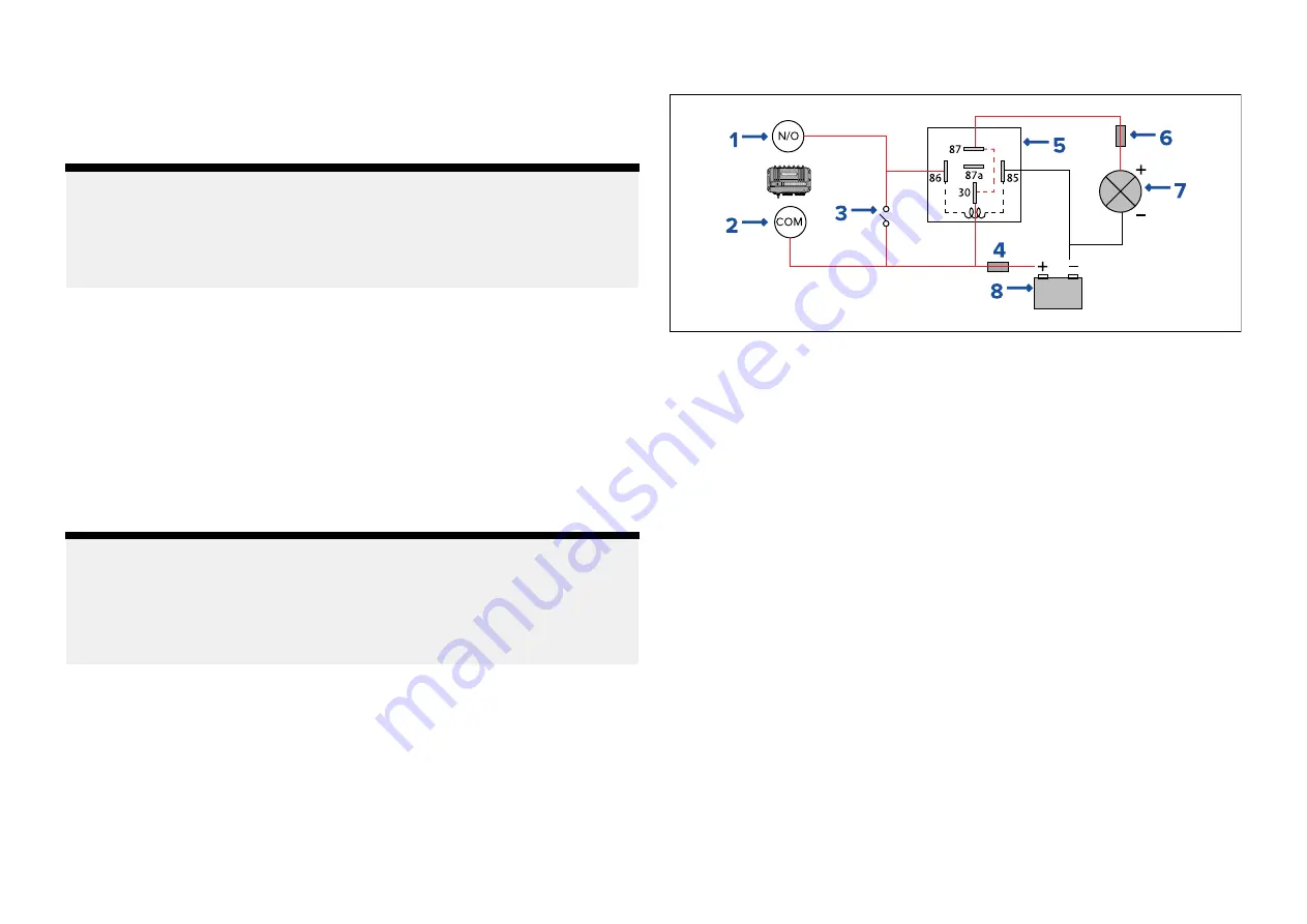
The connection diagram is provided as an example of how the to connect
an output channel (items 1 and 2) via a relay (5) to control a device. The
other components in the diagram may not reflect your installation and
sound electrical judgement should always be used when attempting to
connect the router’s output channels.
Example automotive 4 or 5 pin relay type B connection diagram
1.
Router output channel Normally Open terminal (e.g.: Output 1 White wire)
2. Router output channel Common terminal (e.g.: Output 1 Black wire)
3.
Parallel switch
4.
Suitably rated power supply fuse
5. Automotive 5 pin relay
•
30
— High power feed
•
86
— Relay coil feed (Trigger wire)
•
85
— Relay coil ground
•
87
— High power output (normally open contact)
•
87a
— High power output (normally closed contact)
6. Suitably rated device fuse
7.
Device (e.g.: lighting)
8. Power supply
45


