Chapter 5: Installation
45
Flush mounting
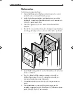
To fit a flush mount control head:
1.
Ensure that the panel on which you intend to mount the control
head is between 3 mm and 20 mm thickness.
2.
Apply the flush mount template (supplied near the rear of this
handbook) to the selected location and mark out the aperture into
which the control head will sit.
3
Cut out the aperture (3) for the control head and remove the
template.
4.
Peel off the protective sheet from the self-adhesive gasket (4) then
stick the gasket into position on the rear of the control head bezel.
D4585-1
5
3
4
6
1
5.
Screw the two fixing studs (1) into the threaded sockets on the rear
of the control head.
6.
Pass the cables (SeaTalk, power, compass etc.) through the
bulkhead and connect them to the appropriate terminals (see
relevant subsection for connection details).
7.
Mount the assembled control head, studs, and gasket into the
panel.
8.
Locate the bracket (6) onto the fixing studs and secure the
assembly to the panel with the thumb-nuts (5). Tighten the thumb
nuts BY HAND. Do NOT use a wrench.
136_3c05.p65
14/06/99, 10:17
45
Summary of Contents for ST5000 Plus
Page 2: ...ST5000 Plus SailPilot Owner s Handbook Document number 81136 4 Date May2001...
Page 3: ......
Page 11: ...viii ST5000PlusSailPilotOwner sHandbook...
Page 41: ...28 ST5000PlusSailPilotOwner sHandbook...
Page 43: ...30 ST5000PlusSailPilotOwner sHandbook 1 1 OR Adjusting User Setup Values...
Page 48: ...Chapter4 CustomisingtheST5000Plus 35 1 1 OR D3583 1a...
Page 83: ...70 ST5000PlusSailPilotOwner sHandbook...
Page 85: ...72 ST5000PlusSailPilotOwner sHandbook...
Page 93: ......
Page 94: ...Shaded area to be removed TOP 109 mm Flush Mount Template 114 mm 4 holes 6 mm diameter D4437 2...
Page 95: ......
Page 96: ...RUDDER POSITIONED AMIDSHIPS CABLE POSITION DRILL THREE 3MM 1 8IN HOLES D3440 1...
Page 97: ......

