Chapter 4: Customising the ST5000 Plus
29
Chapter 4: Customising the ST5000 Plus
The ST5000 Plus provides setup and configuration options that are
used to adjust the settings for the ST5000 Plus itself, the compass, and
the autopilot.
Note: You should perform the post installation procedures described
in Chapter 6 before adjusting any other calibration features.
There are three setup levels:
• User Setup, which controls compass setup, rudder calibration and
the ST5000 Plus display features
• Intermediate Setup, which displays version number information
• Dealer Setup, which controls the autopilot settings, and also the
calibration lock which can be used to prevent accidental access to
User and Intermediate Setup
The ST5000 Plus is calibrated at the factory to provide stable
performance for most yachts. Although many of the setup and
calibration features available in the ST5000 Plus can be fine tuned, it
should not normally be necessary to adjust the Dealer Setup values
once the initial installation and trials have been performed.
4.1 User setup
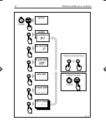
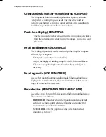
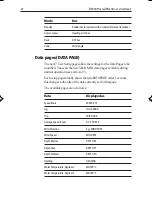
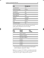
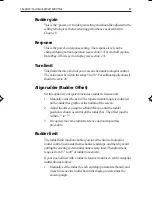
The flow chart on the following page shows the User Setup control
procedure, and the setup screens with their default settings. Information
on the functions of the different settings is given in the remainder of this
section.
The following points should be considered:
• Make sure that the autopilot is in Standby mode before you access
User Setup
• If the
CAL LOCK
screen is displayed instead of the initial page, you
need to turn off the lock feature in Dealer Setup
• Setup options are always saved on exit
136_3c04.p65
14/06/99, 10:16
29
Summary of Contents for ST5000 Plus
Page 2: ...ST5000 Plus SailPilot Owner s Handbook Document number 81136 4 Date May2001...
Page 3: ......
Page 11: ...viii ST5000PlusSailPilotOwner sHandbook...
Page 41: ...28 ST5000PlusSailPilotOwner sHandbook...
Page 43: ...30 ST5000PlusSailPilotOwner sHandbook 1 1 OR Adjusting User Setup Values...
Page 48: ...Chapter4 CustomisingtheST5000Plus 35 1 1 OR D3583 1a...
Page 83: ...70 ST5000PlusSailPilotOwner sHandbook...
Page 85: ...72 ST5000PlusSailPilotOwner sHandbook...
Page 93: ......
Page 94: ...Shaded area to be removed TOP 109 mm Flush Mount Template 114 mm 4 holes 6 mm diameter D4437 2...
Page 95: ......
Page 96: ...RUDDER POSITIONED AMIDSHIPS CABLE POSITION DRILL THREE 3MM 1 8IN HOLES D3440 1...
Page 97: ......


