background image

Chapter 2: Basic Operation

3

Chapter 2: Basic Operation

This chapter first provides summary diagrams of the key functions and
screen layout. It then gives operating instructions for engaging the
autopilot and using Auto mode, changing the lighting, and displaying
Data Pages.

2.1 Key functions

The autopilot is controlled using simple push-button operations, all of
which are confirmed with a beep. In addition to the main single key
functions, there are several dual key functions.

TRACK
Press for Track 
mode from Auto

AUTO
Press for Auto mode

DISP
Press for 
Data Page

STANDBY
Press for Standby
mode

Course Change Keys

Port 1˚ Starboard 1˚

Port 10˚ Starboard 10˚

STANDBY plus AUTO

Press for Vane mode

-1 plus +1

Press for Response level

+1 plus +10
Press together
for AutoTack
to starboard

-1 plus -10
Press together
for AutoTack
to port

Press to accept 
waypoint advance

Press for 1 second
to skip waypoint

Press for 1 second 
for Last Heading

Press again to 
accept Last Heading

Press for 1 second 
for lamp control

Press and hold for 
Setup modes

D3447-1

Press for 1 second

for Rudder Gain

Press for 1 second for Last Wind

Press again to accept Last Wind

• The autopilot always powers up in Standby mode.

• Course changes can be made at any time using the 

–1, +1, –10

 and

+10

 keys.

• You can return to manual steering at any time by pressing 

standby

.

136_3c02.p65

14/06/99, 10:16

3

Summary of Contents for ST5000 Plus

Page 1: ...Distributed by Any reference to Raytheon or RTN in this manual should be interpreted as Raymarine The names Raytheon and RTN are owned by the Raytheon Company...

Page 2: ...ST5000 Plus SailPilot Owner s Handbook Document number 81136 4 Date May2001...

Page 3: ......

Page 4: ...Preface i Rudder Reference Unit ST5000 Plus Control Head Boat s Electrical Distribution Panel SailPilot Fluxgate Compass SeaTalk Instruments D3559 1...

Page 5: ...To the best of our knowledge the information contained within this handbook was correct as it went to press A great deal of care has been taken to ensure that this handbook is as accurate as possible...

Page 6: ...Using Auto mode 5 Engaging the Autopilot Auto 5 Disengaging the autopilot Standby to return to hand steering 5 Changing course in Auto mode 6 Dodging obstacles in Auto mode 6 Returning to the previou...

Page 7: ...ating a dodge manoeuvre 18 Cancelling a dodge manoeuvre 18 Safety 18 Position confirmation at the start of a passage 19 Verifying computed positions 19 Plot frequency 19 Setting waypoints 19 General 1...

Page 8: ...rm 27 Man overboard MOB 27 Chapter 4 Customising the ST5000 Plus 29 4 1 User setup 29 Compass deviation correction 31 Deviation display 31 Heading alignment 31 Heading mode 31 Bar selection 31 Data pa...

Page 9: ...5 2 Control head 43 Siting 43 Mounting procedure 43 Surface mounting 44 Flush mounting 45 Cable connectors 46 Power supply connection 46 Connection to the SeaTalk bus 47 SeaTalk Cables 47 Cable Types...

Page 10: ...59 6 1 Functional test 59 Switch on 59 Operating sense 60 Navigation interface GPS Decca Loran 60 Wind transducer interface 61 SeaTalk interface 61 6 2 Dockside procedure 62 6 3 Initial sea trial 62 E...

Page 11: ...viii ST5000PlusSailPilotOwner sHandbook...

Page 12: ...wtomakeadjustmentstocustomise theautopilottoyourparticularvessel Chapter5 Explainshowtoinstallyourautopilotanditscomponents Chapter6 Coversfunctionaltestinganddocksideproceduresafter installation andi...

Page 13: ...kedautopilotheadingsteersyouclearofallobstacles Make properallowanceforTidalSet theautopilotcannot EvenwhenyourautopilotislockedontothedesiredTrackusinga radionavigationreceiver alwaysmaintainalogandm...

Page 14: ...avigator GPS Decca Loran transmittingNMEA0183data Therearefouroperatingmodes Standby Autopilotdisengaged Auto Autopilotengagedandlockedontoaheading Track Autopilotmaintainsatrackbetweentwowaypointscre...

Page 15: ...riveunit highcurrentFETdrive Currentconsumption Standby 60 mA lessthan200 mAwithfulllighting Auto between0 5 Aand1 5 Adependingondrivetype boattrim helmloadandsailingconditions Operatingtemperature 0...

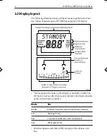
Page 16: ...ress for Standby mode Course Change Keys Port 1 Starboard 1 Port 10 Starboard 10 STANDBY plus AUTO Press for Vane mode 1 plus 1 Press for Response level 1 plus 10 Press together for AutoTack to starbo...

Page 17: ...on Indicator Thebargraphatthebottomofthedisplayisnormallyarudderbar Ifithasbeensetasadirection to steerindicator thedisplaydepends onthecurrentmode asfollows Mode Bar Standby Rudder bar for systems wi...

Page 18: ...rience thatcan ifyou arenotcareful leadto therelaxation ofthe permanentwatch ApermanentwatchMUSTbemaintainedno matterhowcleartheseamayappeartobe Remember alargeshipcantraveltwomilesinfiveminutes just...

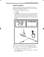
Page 19: ...thascontrol Example a30 coursechangetoport press 10threetimes Dodging obstacles inAuto mode Inordertoavoidanobstaclewhenyourvesselisunderautopilot control selectacoursechangeintheappropriatedirection...

Page 20: ...viouslockedheading LASTHDG isdisplayedfor7seconds 1 Note Adirection to steerindicatorisdisplayedto showyouthe directionthevesselwillturn 2 Toacceptthisheading andresumetheoriginalcourse pressauto once...

Page 21: ...eystogethertotacktostarboard AutoTack to port Pressthe 1and 10keystogethertotacktoport Off course alarm Theoffcoursealarmwillsoundifthelockedautopilotheadingandthe vessel scurrentheadingdifferformoret...

Page 22: ...adingpriortoengagingtheautopilot Course changes under autopilot control Itisimportanttounderstandtheeffectofsuddentrimchangeson steeringperformance Whenasuddentrimchangeoccurs due for example toweathe...

Page 23: ...toheeloverexcessively Easethemainsheettravellertoleewardtoreduceheelingand weatherhelm Ifnecessary reefthemainsailalittleearly Itisalsoadvisable wheneverpossible toavoidsailingwiththewind deadasternin...

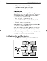
Page 24: ...ost whenthe unit is switchedoff Thekeysarestilllitatacourtesylevelwhenthedisplaylightingisoff 2 5 Data pages Thedispkeyisusedtocycle pages ofSeaTalkorNMEAdata Once aDataPageisselected thispagebecomest...

Page 25: ...ction5 1 Iftherequireddataforapageisnotavailable dashesaredisplayed insteadofavalue Mostdisplaysarerepeateddata andcannotbeadjusted The exceptionsaretheResponseandRudderGainpages ifselectedfor display...

Page 26: ...el isfromaplannedtrack from a ASeaTalknavigationinstrumentorchartplotter or b Anon SeaTalknavigationsystemtransmittingdatainthe NMEA0183format thiscanbeconnecteddirectlytotheST5000 PlusNMEAinput asdes...

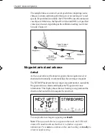
Page 27: ...entlockedheading displayed Afterashortdelayfordataacquisition theWaypoint Advancealarmwillsound andthedisplaywillshowtheplanned bearingtowaypointalternatingwiththedirectioninwhichtheboat willturn Note...

Page 28: ...owspeeds theeffectoftidalstreamsisfarmoresignificant thanit isathigherspeeds Provided thetidalflowislessthan35 of the vessel s speed no noticeable difference should occur in the performance of Track m...

Page 29: ...alarmsoundsiftheXTEexceeds0 3nm Thedirectionoftheerrorisidentifiedasport Pt orstarboard Stb Tocancelthealarmandleavetrackmode press standbytoreturn tohandsteering orautotoreturntoAutomodeandretainthe...

Page 30: ...Arrival Asthevesselarrivesatthetargetwaypoint thenavigationreceiver shouldselect manuallyorautomatically thenexttargetwaypoint TheST5000Plusdetectsthenewtargetwaypointnumber soundsthe WaypointAdvancea...

Page 31: ...e manner the alarm will continue to sound and the current heading will be maintained Dodges Fullcontrolisstillavailablefromthekeypadwhentheautopilotisin Trackmode Initiatingadodgemanoeuvre InTrackmode...

Page 32: ...eachtrack Checkupto0 5 nmeachsideofthetracktoensurethatthereareno hazardswithinthezone Note In order for the waypoint advance function to work successfully the last four characters of adjacent waypoin...

Page 33: ...rentwindangle TheboatheadingisadjustedbytheST5000Plustomaintainthe lockedapparentwindangle Adjusting the locked wind angle Thelockedwindanglecanbeadjustedbychangingcourseusingthe 1 1 10and 10keys Fore...

Page 34: ...lwillturn 2 Checkthatitissafetoturnontothiscourse 3 Toacceptthisapparentwindangle pressstandbyandauto togetherwithin7seconds Ifyoudonotacceptthepreviouswindwithinthistime the autopilotwilllockontothec...

Page 35: ...henewapparentwindangle UsingAutoTack inVane mode Theautomatictackfunctiontacksthevesselthroughasetangle the factorydefaultis100 Thelockedheadingcanthenbeadjusteduntil therequiredapparentwindangleisach...

Page 36: ...elevelandruddergain as specifiedinDealerSetup arerestoredwheneverthesystemispowered on Changing the response level AutoSeastate Theresponselevelcontrolstherelationshipbetweentheautopilot s coursekeepi...

Page 37: ...Alarms Thissectionsummarisesthealarms inorderofpriority thatare reportedbythe ST5000Plus Pressstandbytoclearanalarmandreturntohandsteering unless otherwisestated SeaTalkfailure STLKFAIL Thissilentalar...

Page 38: ...ducerfails theautopilotisunabletoturntherudder Thisoccursiftheweather loadonhelmistoohigh oriftherudderpositionispastthepreset rudderlimitsortherudderend stops Datanotreceived NODATA Thisalarmisdispla...

Page 39: ...splaysthebearingtothenextwaypointandthedirectioninwhichthe boatwillturntotakeupthatbearing Checkthatitissafetoturnontothenewtrack andpresstrackto acceptthewaypointadvance Alternatively tocancelthealar...

Page 40: ...ilencethealarmandresetthetimerto 4minutes Pressinganyotherkeyresetsthetimerandperforms thekey snormalfunction 4 ToclearWatchmode pressdisptodisplayadifferentpage or pressstandby Note You cannot engage...

Page 41: ...28 ST5000PlusSailPilotOwner sHandbook...

Page 42: ...hcanbeusedtopreventaccidentalaccessto UserandIntermediateSetup TheST5000Plusiscalibratedatthefactorytoprovidestable performanceformostyachts Althoughmanyofthesetupand calibrationfeaturesavailableinthe...

Page 43: ...30 ST5000PlusSailPilotOwner sHandbook 1 1 OR Adjusting User Setup Values...

Page 44: ...screenisusedtoaligntheautopilotcompass withtheship scompass Steeryourvesselontoaknownheading Adjustthedisplayedheadingusingthe 1 1 10and 10keys Checktheautopilotdisplayonvariousheadingsandadjustas nec...

Page 45: ...agesavailableduring normaloperation seesection2 5 EachsetuppageinitiallyshowsthetitleDATAPAGE After1second thischangestothetitleofthedatacurrentlysetforthatpage Theavailablepagesareasfollows Data Disp...

Page 46: ...es Datais displayedintheunitsdefinedbytheselectedpage Thedefaultsettingsare Data Default New Page Setting Setting 1 XTE Cross Track Error 2 BTW Bearing to Waypoint 3 DTW Distance to Waypoint 4 NOT USE...

Page 47: ...factorydefaultsettingswillprovidesafeperformancefor theinitialseatrial andfinetuningisnotnormallyrequired TheflowchartonthefollowingpageshowsyouhowtoenterDealer Setup scrollthroughthesetupdisplays adj...

Page 48: ...Chapter4 CustomisingtheST5000Plus 35 1 1 OR D3583 1a...

Page 49: ...Align Rudder 7to 7 0 Rudder limit 15to40 30 Offcoursealarm 15to40 20 AutoTack angle 40to125 100 AutoTrim OFF 1to4 3 Drive type 1 soft drive or 1 2 hard drive Variation 30to 30 0 AutoAdapt N S OFF OFF...

Page 50: ...ludesarudderreferenceunit 1 Manuallycentrethehelm Thereportedrudderangleisindicated ontherudderbargraphicatthebottomofthescreen 2 Adjusttheoffset usingthe 1and 1keys untiltherudder positionisshownasce...

Page 51: ...ratesifthepilotstraysoff coursebymorethanthealarmanglelimitformorethe20seconds The valuemustbewithin15 to40 andcanbeadjustedin1 steps AutoTack angle TheAutoTackangleistheanglethroughwhichthevesselwill...

Page 52: ...DecreasetheAutoTrimleveliftheautopilotgivesunstablecourse keepingorexcessivedriveactivitywithachangeintheheelangle IncreasetheAutoTrimleveliftheautopilotreactsslowlytoa headingchangeduetoachangeintheh...

Page 53: ...ntlatitude tothenearestdegree Note IfvalidlatitudedataisavailableviaSeaTalkorNMEA itwillbe used instead of this calibration value Rudder damping Setthisoptionifyoursystemincludesarudderreferenceunitan...

Page 54: ...installationisrequiredtoensurethatperformanceisnotcompromised Althougheveryefforthasbeentakentoensurethattheywillperform underallconditions itisimportanttounderstandwhatfactorscould affecttheoperatio...

Page 55: ...inthesameposition Suppression Ferrites Thefollowingillustrationshowsthetypicalrangeofsuppression ferritesfittedtoRaymarineequipment Alwaysusetheferritesspecified byRaymarine Connections to other equip...

Page 56: ...ipment Mountedwithsufficientspacebehindthebulkheadtoinstallthe cables Note The back cover is designed to breath through the cable boss to prevent moistureaccumulation Thismustbe protectedfrom the weat...

Page 57: ...mm 5 32 in diameterholesforthefixingstuds 4 Usea90 mm 3 5 in diametercuttertodrilltheholeforthecable boss 1 5 Peel off the protective sheet from the self adhesive gasket 4 then stick the gasket into p...

Page 58: ...el off the protective sheet from the self adhesive gasket 4 then stick the gasket into position on the rear of the control head bezel D4585 1 5 3 4 6 1 5 Screw the two fixing studs 1 into the threaded...

Page 59: ...boot incorrectfittingwillgiveintermittentcontact whichwillleadtofaultyautopilotoperation Power supply connection Thecontrolheadrequiresitsowndedicatedpowersupply Itcannot sourcepowerfromSeaTalk andmus...

Page 60: ...ng slower response to course changes and corrections Connection to the SeaTalk bus SeaTalkcablesarenotsuppliedwiththeequipment asdifferent installationshavedifferentcablingrequirements SeaTalkCables T...

Page 61: ...92 1 SeaTalk Bus Power Supply Autopilot Control Head rear 5 3 Fluxgate compass Correctpositioningofthefluxgateiscrucialifultimateautopilot performanceistobeachieved Thefluxgateshould tominimisegimbald...

Page 62: ...aringcompassshouldbefixedinthechosen positionandthevesselswungthrough360 Differencesbetweenthehandbearingcompassandthemain steeringcompassshould ideally notexceed20 onanyheading Mounting location for...

Page 63: ...ing the fluxgate compass Attachthefluxgatecompasstoabulkheadusingthefourself tapping screwsprovided Vertical D193 1 Note A label is supplied to warn people that the compass is mounted behind or below...

Page 64: ...orcolour totheCompass terminals D3282 1 5 4 Rudder reference transducer ArudderreferencetransducerissuppliedwiththeST5000Plus SailPilot Thisdeviceprovidestheautopilotwithaccurateinformation ontheposit...

Page 65: ...lationtoensurethetransducerarm isoppositethecableentrywhentherudderisamidships Failureto positionthearmcorrectlycouldresultindamageifthearmisdriven ontoitsendstopsbythesteeringsystem Control dimension...

Page 66: ...Usetheself tappingscrewstosecurethetillerpintothetillerarm 4 Cutthethreadedrodtotherequiredlength 5 Screwonthelocknutsandballpinsockets 6 Pressthesocketsontothetillerpins 7 Movetherudderfromsidetoside...

Page 67: ...usfortheSailPilotshouldbe250mm 10in Thedriveunitshould ideally becoupledtotherudderstockviaan independenttillerarm forexample EdsonandWhitlockoffera standardfitting Itispossibletocouplethedrivespushro...

Page 68: ...beboltedtoasubstantialframe member alwaysover engineertoensurereliabilityand maintenanceofthecorrectalignment Lock washer Tiller arm Fixing bolt flange Hole dia 0 52in 13mm D761 2 1 Usingtheadaptorpin...

Page 69: ...theclutch Useasuitablecable refertothefollowingtable toconnectthedrive unittotheST5000PlusControlhead asshown Cable length Copperarea AWG Upto2 5m 8ft 2 5 mm2 14 Upto4 m 13 ft 4 0 mm2 12 Upto6 m 19 5...

Page 70: ...tsare showninthetableattheendofthissection Cabling TheNMEAdataportisontherearoftheST5000Plusandshouldbe connectedtoaPositionTransducerorWindInstrument Red Data In ve Blue Data In ve D3374 1 Navigator...

Page 71: ...WV Speed Through Water VHW Depth DBT Water Temperature MTW Note The autopilot only decodes the last four characters of waypoint names Therefore if long waypoint names are used the last four characters...

Page 72: ...edwiththerudder Initialseatrial toswingthecompassandaligntheheading check theautopilot soperationandchecktheruddergain Furthercustomisationcanbeperformedaftertheseatrial asdescribed inChapter4 6 1 Fun...

Page 73: ...ive back or starts to hunt back and forth you need to increase the Rudder Damping option in DealerSetup seeChapter4 Navigation interface GPS Decca Loran IftheST5000Plusisinterfacedtoanavigator viaitsN...

Page 74: ...asfollows Pressstandbyand autotogether TheST5000PlusshoulddisplaytheVanemodescreen withthe lockedwindangleandlockedheadingasshown Alternatively ifthewinddataisnotreceived theST5000Pluswill displayaNOD...

Page 75: ...tedrudderangleisasclose tozeroaspossible Thentightentheboltsagain 4 Fineadjustment toalignthedisplayandhelmaccurately is achievedusingtheAlignrudderoptioninDealerSetup see Chapter4 However thiscannotb...

Page 76: ...ommendedlevels asdescribedin Chapter4 Inconditionsoflightwindandcalmwater sothatautopilot performancecanbeassessedwithouttheinfluenceofstrongwinds orlargewaves Inwatersclearofanyobstructions Note At a...

Page 77: ...User Setupentrypage D3448 1 IfCALLOCKisdisplayed youneedtoturnoffthelockfeature containedinDealerSetup seeChapter4 3 PressthedispkeytomoveontotheSwingCompasspage D3460 1 4 Pressthe 1or 1keytochangethe...

Page 78: ...ectionprocessbypressingthedispkeyto moveontotheDEVIATIONscreen Ifyouwishtoattemptdeviationcorrectionagain youcanstep backtotheSwingCompasspageorkeeppressing disptocycle throughthecalibrationoptionsunt...

Page 79: ...isplayed at all you should consider moving the fluxgate compass to a betterlocation 7 PressthedispkeytomoveontotheHeadingAlignmentpage D3459 1 ALIGN HDG 8 Usethe 1and 1 keys orthe 10and 10keys toincre...

Page 80: ...een as described above Iftheaverageheadingerrorismorethan5 youshouldperformthe compassdeviationcorrectionprocedureagain circlingslowerandin movefavourableconditions Checking autopilot operation Having...

Page 81: ...llresultin understeerwhichgivessluggishsteeringperformance B Ifthe vesseltakesalongtimetomaketheturnandthereisno overshootthentheruddersettingistoolow Theseactionsaremosteasilyrecognisedincalmseacondi...

Page 82: ...Chapter6 PostInstallationProcedures 69 4 Onceyouhavedeterminedthecorrectsetting changethedefault RudderGainsettinginDealerSetup asdescribedin Chapter4 Customising the ST5000 Plus...

Page 83: ...70 ST5000PlusSailPilotOwner sHandbook...

Page 84: ...isbeingsuppliedtotheequipment AlwaysreportanyEMCrelatedproblemtoyournearestRaymarine dealer Wewilluseanysuchinformationtoimproveourquality standards Advice Shouldanydifficultiesarisewiththisproduct pl...

Page 85: ...72 ST5000PlusSailPilotOwner sHandbook...

Page 86: ...comeonto course Ruddergaintoolow Vesselovershootswhenturningontoanewcourse Ruddergaintoohigh TheautopilotappearstobeunstableinTrackmode ortrack holding is slow Iftidespeedexceeds35 ofboatspeed andboat...

Page 87: ...towaypointinformationreceivedfromthenavigator Aseriesofrotatingdashesaredisplayedonscreen Compassdeviationcorrectionisrunning Thedisplayshowsaseriesofstationarydashes Dataisnotbeingreceived checktheca...

Page 88: ...mode 22 AutoTrim Default setting 38 B Bar graph 4 C Cabling 71 Calibration 29 40 Calibration lock 36 Changing course 6 Compass alignment 66 Compass deviation correction 31 63 Course changes 6 operati...

Page 89: ...Engaging the autopilot 5 F Fault finding 73 Functional test 59 60 G Graph use 31 H Hand steering 5 Heading 7 Heading alignment 31 Heading alignment adjustment 67 Heading mode 31 I Illumination 10 Ins...

Page 90: ...alarm 25 O Off Course alarm 8 Default angle 38 Operating modes 1 Operating sense 60 P Performance 23 Pilot type 36 Previous heading 7 R Response level 23 Default setting 37 Rudder bar 31 Rudder dampi...

Page 91: ...67 Testing the system 59 60 Tidal stream compensation 16 Track acquisition 13 Track mode 13 14 Turn limit 37 U User Setup 29 V Vane mode 19 20 Variation 39 W Watch alarm 26 Waypoint arrival and advanc...

Page 92: ...Machine hole 90mm 3 54in diameter Drill 5mm 3 16in Drill 5mm 3 16in Surface mount template D3441 2a...

Page 93: ......

Page 94: ...Shaded area to be removed TOP 109 mm Flush Mount Template 114 mm 4 holes 6 mm diameter D4437 2...

Page 95: ......

Page 96: ...RUDDER POSITIONED AMIDSHIPS CABLE POSITION DRILL THREE 3MM 1 8IN HOLES D3440 1...

Page 97: ......

Page 98: ...in impeller carriers impellers impeller bearings and impeller shaft are specifically excluded from this Warranty Magnetrons Cathode Ray Tubes CRT TFT Liquid Crystal Displays LCD and cold cathode fluo...

Page 99: ...elephone 1 800 539 5539 Ext 2333 or 1 603 881 5200 Ext 2333 Customer Support Telephone 44 0 23 9271 4713 Fax 44 0 23 9266 1228 Technical Support Telephone 1 800 539 5539 Ext 2444 or 1 603 881 5200 Ext...

Reviews: