5.5 Handset mounting
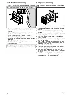
In order to mount the handset clip follow the steps below.
0
0
0
0
0
0
0 0
0
0
0
0
0
0
0
0
0
0
0
0
0
0
0
0
0
0
D12610-1
0
0
0
0
0
0
1. Check the selected location for the handset clip, a clear flat
area is required, with sufficient space around it to place and
remove the handset.
2. Using a pencil, offer up the handset clip to the desired
location and mark the location of the screw holes on the
mounting surface.
3. Drill the mounting holes using a suitable size drill bit.
4. Hold the clip in place and secure using the screws provided.
Note:
Drill bit, tap size and tightening torque is dependent on
the thickness and type of material the unit is to be mounted on.
Pass-through panel plate mounting
When installing the handset use the supplied, handset extension
cable kit to pass the cable through a panel (e.g. bulkhead).
D12192-1
1
5
2
6
7
3
4
1
Splash-proof cap
2
Mounting screws x3
3
Mounting plate
4
Gasket
5
Nut
6
Washer
7
Extension cable connector
1. Check the selected location for the mounting of the handset
cable extension mounting plate, a clear flat area is required.
2. Using a pencil, offer up the mounting plate to the desired
location and mark the location of the screw holes and the
center hole on the mounting surface.
3. Drill the mounting holes using a suitable size drill bit.
4. Drill the center hole using a 25 mm (1 in.) hole cutting saw.
5. Hold the clip in place and secure using the screws provided.
6. Pull the connector end of the cable through the hole in the
mounting panel.
Note:
The handset extension cable includes a speaker cable.
If you are not connecting an external passive speaker then
cover the speaker cable with waterproof tape or sealant to
prevent corrosion.
7. Insert the washer (labelled 6 in the diagram below) over the
end of the connector.
8. Insert the gasket (labelled 4 in the diagram above) over the
end of the connector.
9. Insert the mounting plate (labelled 3 in the diagram above)
over the end of the connector, ensuring that the screw holes
are aligned with the respective holes in the gasket and the
mounting panel.
10. Place the nut (labelled 5 in the diagram above) over the
connector and tighten clockwise using a 13/16 in. (21 mm)
socket wrench.
11. Align the small end of the splash-proof cap (labelled 1 in the
diagram above) with one of the screw holes on the gasket.
12. Secure the mounting plate to the mounting surface using the
supplied screws.
13. Attach the handset or microphone to the cable connector and
rotate clockwise to secure.
14. Connect the opposite end of the cable to the required
connector either on the base station or to another
pass-through panel plate connector.
Note:
Drill bit, tap size and tightening torque is dependent on
the thickness and type of material the unit is to be mounted on.
Location and mounting
29
Summary of Contents for Ray260
Page 2: ......
Page 4: ......
Page 18: ...18 Ray260 ...
Page 30: ...30 Ray260 ...
Page 52: ...52 Ray260 ...
Page 60: ...60 Ray260 ...
Page 64: ...64 Ray260 ...
Page 68: ...68 Ray260 ...
Page 72: ...72 Ray260 ...
Page 80: ...80 Ray260 ...
Page 92: ...92 Ray260 ...
Page 93: ......
Page 94: ...www raymarine com ...

