3-22
Operation with Minimum Function Handset
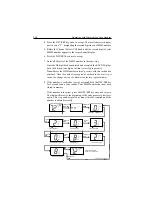
1. Press and release the DSC/PRI and D/L
/
I.C. keys simultaneously to
place the unit in DSC mode. “70” appears in the large channel display,
the DSC indicator illuminates, and ”in” appears in the small channel
display to designate Individual Call.
2. Press and release the SCAN/MEM key. A letter appears in the small
channel display, which is associated with one of the other ship’s MMSI
numbers in the phonebook.
3. If you wish to use the use the other ship’s MMSI number associated
with this letter, press DSC/PRI.
4. To use a different letter, rotate the Channel Selection Knob until the
desired letter is displayed. Press DSC/PRI to select this letter.
5. After you have selected the other ship’s MMSI number, the radio
prompts you for the working channel to communicate on. The large
character display shows the last used channel number and a “W”
appears in the small channel display.
6. Using the Channel Select (CH) knob on the front panel, select the
desired channel, and press the DSC/PRI key once. The TX indicator
on the LCD flashes, indicating the RAY215E is ready to transmit.
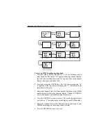
7. Press the PTT key to send the Individual Ship’s Call. After the digital
“packet” of information is sent, the radio waits for an acknowledgment
from the targeted ship or station.
8. If the target station acknowledges, a tone sounds and “ACK”
illuminates on the LCD. After 2 seconds, the RAY215E switches to
the previously selected working channel.
or
If the call is not acknowledged, exit the DSC mode by pressing 16
key.
Note:
The operation is cancelled if the 16 key is pressed or if no keys
are pressed for 60 seconds during any part of this process.
Summary of Contents for Ray215e
Page 1: ...O w n e r s H a n d b o o k VHF Radio Ray215e...
Page 2: ...RAY215E Modular VHF Radio Owner s Handbook Document number R49018_2 Date April 2002...
Page 3: ......
Page 23: ...2 10 Installation Figure 2 6 Typical Grounding Method...
Page 115: ...4 60 Operation with Full Function Handset...
Page 121: ...5 6 Maintenance This page intentionally left blank...
Page 122: ...5 7 Maintenance 5 4 Drawings Assembly Drawing...
Page 123: ...5 8 Maintenance Block Diagram RF PCB...
Page 124: ...5 9 Maintenance Control PCB...

