3-12
Operation with Minimum Function Handset
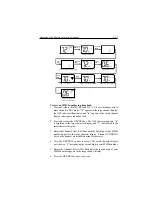
To perform the memory reset:
1. Turn the radio OFF.
2. Press and hold the SCAN/MEM key.
3. While continuing to hold the SCAN/MEM key, turn the radio ON.
The LCD remains blank for 2 seconds, CL appears momentarily, then
the unit switches to channel 16.
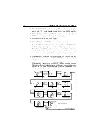
3.5.13 Scan Modes
The RAY215E is equipped with two types of scan options: All Scan and
Memory Scan. How these options are initiated depends upon whether
there are any channels stored in memory.
All Scan Mode
If no channels are stored in memory when the SCAN/MEM key is pressed,
the radio begins scanning all channels (except weather channels) as long
as no signal is received. If a signal is received, the scan stops on the
receiving channel as long as it is present. If the signal is lost for five
seconds or SCAN/MEM is pressed, the radio resumes scanning. SCAN
is displayed on the LCD while the Scan mode is active.
If the SCAN/MEM key is pressed again while SCAN is flashing, the All
Scan Standby state is suspended and the unit returns to the normal state.
To cancel the scan mode, press the SCAN/MEM key once.
Memory Scan Mode
If one or more channels are stored in memory when the SCAN/MEM key
is pressed, SCAN and MEM begin to flash simultaneously on the LCD. If
no other key is pressed within three seconds, SCAN and MEM stop
flashing and the radio begins scanning all channels currently stored in
memory. As with All Scan, if a signal is received, the scan stops on the
receiving channel until the signal is lost for five seconds or SCAN/MEM
is pressed, and then the radio resumes scanning. To cancel memory scan,
press and release SCAN/MEM.
If there are channels stored in memory but All Scan operation is desired,
press SCAN/MEM again within the 3 second period while the SCAN and
MEM indicators are flashing.
Note:
Scan modes are disabled when the ATIS operation is active.
Summary of Contents for Ray215e
Page 1: ...O w n e r s H a n d b o o k VHF Radio Ray215e...
Page 2: ...RAY215E Modular VHF Radio Owner s Handbook Document number R49018_2 Date April 2002...
Page 3: ......
Page 23: ...2 10 Installation Figure 2 6 Typical Grounding Method...
Page 115: ...4 60 Operation with Full Function Handset...
Page 121: ...5 6 Maintenance This page intentionally left blank...
Page 122: ...5 7 Maintenance 5 4 Drawings Assembly Drawing...
Page 123: ...5 8 Maintenance Block Diagram RF PCB...
Page 124: ...5 9 Maintenance Control PCB...

