2-6
Installation
Wire Color
Wire Color
Wire Color
Wire Color
Wire Color
Function
Function
Function
Function
Function
Connects to
Connects to
Connects to
Connects to
Connects to
RED
Power +
Ship's 13.6 VDC power
BLACK
Power
−
YELLOW
S
External speaker
GREEN
Speaker
−
BLUE
NMEA +
Input from position source (GPS, etc.)
PURPLE
NMEA
−
The RED (+) power wire contains a 10 amp in-line fuse.
2.4
Electrical Connections
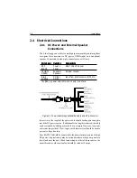
2.4.1 DC Power and External Speaker
Connections
The 6-foot long power cable is a multi-purpose assembly containing three
wire-pairs for connections to DC power, NMEA input, and an optional
speaker. Connections to the 6-pin connector are as follows:
Figure 2-3 Power/External Speaker/NMEA Cable and 6 Pin Connector
In most cases the length of the power cable should be adequate enough to
reach the DC power source. If additional wire length is required, the cable
can be extended by adding more cable as necessary. However, for power
cable runs longer than 15 feet, larger wire diameter size should be used to
prevent voltage line loss.
Your RAY215E should be connected to the nearest primary source of ship's
DC power. A typical source may be a circuit breaker on the power panel or a
fuse block near the unit. When connecting to either of these sources, the
circuit breaker or other in-line fuse should be rated at 10 amps.
Summary of Contents for Ray215e
Page 1: ...O w n e r s H a n d b o o k VHF Radio Ray215e...
Page 2: ...RAY215E Modular VHF Radio Owner s Handbook Document number R49018_2 Date April 2002...
Page 3: ......
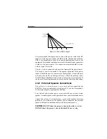
Page 23: ...2 10 Installation Figure 2 6 Typical Grounding Method...
Page 115: ...4 60 Operation with Full Function Handset...
Page 121: ...5 6 Maintenance This page intentionally left blank...
Page 122: ...5 7 Maintenance 5 4 Drawings Assembly Drawing...
Page 123: ...5 8 Maintenance Block Diagram RF PCB...
Page 124: ...5 9 Maintenance Control PCB...


