3-18
Operation with Minimum Function Handset
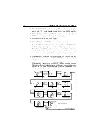
4. Press the DSC/PRI key once to accept. The small character display
now shows a “2”, designating the second digit in your MMSI number.
5. Rotate the Channel Select (CH) knob until the second digit of your
MMSI number appears in the large channel display.
6. Press the DSC/PRI key once to accept.
7. Enter all 9 digits of the MMSI number in the same way.
Once the 9th digit has been entered and accepted, the RAY215E plays
back the 9 digits (one digit at a time) to verify proper entry.
Note:
Ensure the MMSI number entered is correct with this verification
playback. Once the number is accepted as outlined in the next step, it
cannot be changed except by Raymarine factory representatives.
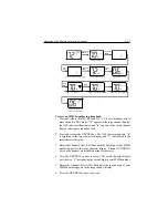
8. If the number is verified as correct, press and hold the DSC/PRI key
for 2 seconds and a tone sounds. Your MMSI number has now been
stored in memory.
If the number is incorrect, press the DSC/PRI key once and release.
The radio will revert to the beginning of the entry process to start over
again. This step can be repeated as many times as required until the
number is entered correctly.
ROTATE
CH
PRESS & REL
DSC
PRESS & REL
DSC
PRESS & HOLD
DSC
MMSI digit
digit position
Select desired digit
Next digit position
Select desired digit
Continue thru last digit position
Radio replays all digits...
MMSI number accepted
PRESS & REL
DSC
Returns to working channel
...through the 9th position
Returns to first digit position
ROTATE
CH
Select desired digit
ROTATE
CH
PRESS & REL
DSC
PRESS & HOLD
DSC
+
D/L
PRESS & REL
SCAN
Summary of Contents for Ray215e
Page 1: ...O w n e r s H a n d b o o k VHF Radio Ray215e...
Page 2: ...RAY215E Modular VHF Radio Owner s Handbook Document number R49018_2 Date April 2002...
Page 3: ......
Page 23: ...2 10 Installation Figure 2 6 Typical Grounding Method...
Page 115: ...4 60 Operation with Full Function Handset...
Page 121: ...5 6 Maintenance This page intentionally left blank...
Page 122: ...5 7 Maintenance 5 4 Drawings Assembly Drawing...
Page 123: ...5 8 Maintenance Block Diagram RF PCB...
Page 124: ...5 9 Maintenance Control PCB...


