4-54
Operation with Full Function Handset
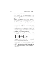
• The ATIS ID number is a ten digit number, beginning with a “9”. The
MY ATIS set up process has you input only the last 9 digits. The leading
“9” is automatically input for you.
To register the ATIS Number into memory:
1. Select the MY ATIS function as described above in Section 4.7.4
Setting Operation.
2. Press the ENT key. The 7-segment display shows
AId
and the dot
matrix display scrolls PLEASE PROGRAM ATIS ID.
3. Press ENT. Nine underscore characters appear, which are placeholders
for the last 9 digits of the ATIS number. The first character place to be
input is flashing.
Pressing the following keys initiate the corresponding operation:
K
K
K
K
Keys
eys
eys
eys
eys
Action
Action
Action
Action
Action
0 - 9 keys
Changes the flashing numeric value, then advances to the next
digit’s place.
ENT key
Advances the (flashing) subject item to the next one without
changing the numeric value. Advances to the next screen after
entering the last (ninth) digit.
CLR key
Returns to the previous subject item. Pressing and holding for 3
seconds exits the operation and returns to the mode before the
Menu Operation began.
4. Input your ATIS number using the numeric keypad.
5. Press the ENT key. The message ENT - ACCEPT, CLR - EXIT scrolls
across the display.
6. Press the ENT key to submit the number. The message ENTER ATIS
ID AGAIN is displayed.
7. Press ENT. The nine underscore placeholders appear once more.
8. Again input the ATIS number with the numeric keypad.
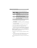
9. Press ENT to submit. If the second ATIS number you input matches
the first, the message ENT - ACCEPT, CLR - EXIT is again displayed.
Summary of Contents for Ray215e
Page 1: ...O w n e r s H a n d b o o k VHF Radio Ray215e...
Page 2: ...RAY215E Modular VHF Radio Owner s Handbook Document number R49018_2 Date April 2002...
Page 3: ......
Page 23: ...2 10 Installation Figure 2 6 Typical Grounding Method...
Page 115: ...4 60 Operation with Full Function Handset...
Page 121: ...5 6 Maintenance This page intentionally left blank...
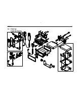
Page 122: ...5 7 Maintenance 5 4 Drawings Assembly Drawing...
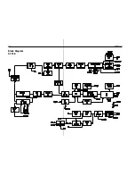
Page 123: ...5 8 Maintenance Block Diagram RF PCB...
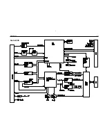
Page 124: ...5 9 Maintenance Control PCB...


