background image

112

Raymarine H6 - Owner’s Manual

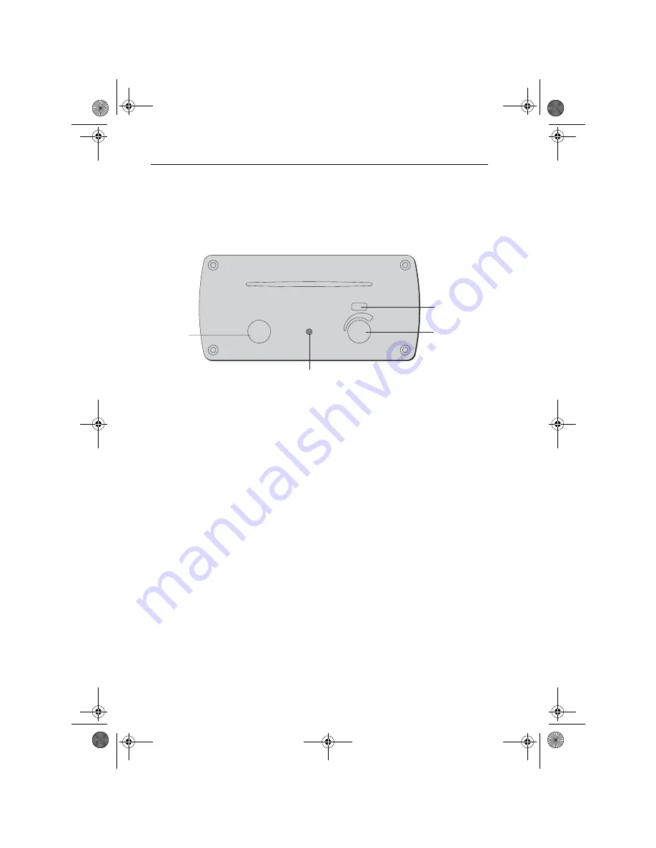
Audio-visual control unit

The audio-visual (AV) control unit provides a master control for the entertainment 
system and can be used to play both CD and DVD’s. The unit has the following 
controls:


Selector switch

 - select OFF, ON or AUX input.

Eject button

 - Press to eject the disk.

Volume control

 - turn to increase/decrease volume levels.

When using the AV control unit, the volume levels for the whole of the 
entertainment system can be controlled from the unit. 

If a CD or DVD is paused or stopped for 30 minutes, the system will enter screen-
saver mode. To return to the CD/DVD, press play for the relevant application on 
the remote control unit, and it will restart.

To eject a disk from the unit, simply press the eject button. There is no need to stop 
playback or turn the disk off using the remote control unit.

off

on

aux

.

Selector

switch

Volume
control

Eject button

Infra-red

sensor

81238_1.book  Page 112  Thursday, September 16, 2004  2:49 PM

Summary of Contents for H6

Page 1: ...Raymarine H6 Owner s Manual Document Number 81238_1 Date September 2004 81238_1 book Page 1 Thursday September 16 2004 2 49 PM...

Page 2: ...star ST40 ST60 Seaclutter Smart Route Tridata and Waypoint Navigation are trademarks of Raymarine Limited Windows Word and Excel are registered trademarks of Microsoft Inc Firewire is a trademark of A...

Page 3: ...he Command Center 3 Controls 3 The User Interface 4 Interface controls 4 Displaying information 9 Getting Started 11 Introduction 11 System start up 11 Adjusting the display screen 12 System set up 13...

Page 4: ...ing the cursor 35 using the waypoints list 35 Moving a waypoint 35 Editing waypoint details 36 Organizing waypoints 36 Transferring waypoints and route data 39 Using routes 43 Introduction 43 Creating...

Page 5: ...celling a MARPA target 69 Viewing MARPA target data 69 Radar Tools and Controls 71 Tools 71 Controls 72 Using sonar 75 Introduction 75 The sonar screen 75 Displaying sonar 76 Changing the screen 76 Ba...

Page 6: ...1 Displaying CCTV 101 Using Online 103 Introduction 103 Getting started 104 Using Navtex 107 Introduction 107 The screen 107 Getting started 108 Receiving messages 108 Using the entertainment system 1...

Page 7: ...es 134 Installing charts 134 C Map NT PC charts from CD ROM 134 Maptech charts 138 Appendix B Radar 141 Introduction 141 What is radar 141 Scanner 141 Maximum radar range 141 Range control 142 Standar...

Page 8: ...ift values 151 Appendix D Technical specification 153 Appendix E List of Abbreviations 165 Appendix F Installation checklist 167 Appendix G Software license 169 Appendix H Disclaimer 171 Raymarine H6...

Page 9: ...s itis not perfect and any part of it can fail GPS accuracy varies between 2 and 50 meters Another limitation to accuracy of the system is digital charts These electronic charts are made by highly ski...

Page 10: ...nnel above head height Avoid looking directly at the antenna as your eyes are the most sensitive part of the body to electromagnetic energy WARNING Product installation This equipment must be installe...

Page 11: ...CAUTION Terrestrial television reception It is the Owner s responsibility to check and comply with local licensing requirements for the reception of terrestrial television in their area of operation C...

Page 12: ...s Manual CAUTION Lifeline transmitter tag Donotovertightenthetransmittertagscrewswhenreplacingthe unit battery as this may result in irreparable damage to the unit 81238_1 book Page xii Thursday Sept...

Page 13: ...ine H6 Italics are used to show names such as those on softkeys e g Gain Instructionsforusingmenuoptionsarewrittenasmenuoption submenu options For example the instructions might read Select Controls R...

Page 14: ...f printing However Raymarine cannot accept liability for any inaccuracies or omissions it may contain In addition Raymarine s policy of continuous product improvement may change specificationswithoutn...

Page 15: ...uld choose the layout of the helm instruments and not the boat builder Following naturally from that the helmsman should be able to have only the instruments displayed that he or she requires for a pa...

Page 16: ...4 hour intervals covering a period of several days giving you a comprehensive presentation of atmospheric and marine conditions Lifeline Crew safety is paramount Lifeline is a positive reporting syste...

Page 17: ...een display functions On screen display control buttons Enable adjustment of the display for example brightness and volume Trackball The trackball consists of Roller ball used to move the cursor aroun...

Page 18: ...interface and its controls Detailed operating instructions are given in the relevant sections of this manual Interface controls Button bar Thebuttonbarislocatedverticallyattheleftsideoftheleft handsc...

Page 19: ...red on data boxes appear minimized in a column on the left screen to the right of the button bar These data boxes can be opened closed floated resized and moved to any position and docked as required...

Page 20: ...in difficult sea conditions Exceptions to this are Position Cross Track Error XTE Rudder angle Positionisalwaysdisplayednumerically XTEandrudderangleasabardialwitha number beneath Position displays l...

Page 21: ...the same for all applications whilst Controls are application specific Tool box The Tool box is displayed by clicking the Tools tab located totheleftofthescreenintheupperborderofanapplication window T...

Page 22: ...osed by clicking the cross at the top rightofthepanel Thecrosswillbeenlargedasyouplacethe cursor over it making operation easy and accurate in difficult sea conditions Manual adjustment When certainso...

Page 23: ...to the object at which you are pointing Displaying information Dialog box Dialog boxes allow you to access various componentstocarryoutaselectedfunction or feature To make a selection from a dialog b...

Page 24: ...your approval or tells you that you need to select an option usually Yes or No or OK Onceyouhaveacceptedthe option the dialog box is automatically removed from the screen Information box Information...

Page 25: ...ure that all peripheral instruments within the system are powered ON 2 Press the button on the front of the Navigation computer to start running H6 3 Press the power button on both displays to ON The...

Page 26: ...justed using as follows D7235_1 Brightness 43 Volume 29 Video source Analogue RGB DV1 Composite S Press do not hold To adjust select Selecting the mode What you see To finish or wait 10 secs Press do...

Page 27: ...ve been determined by Raymarine but your preferences may be different To customize these modes to your preferences see below The pre set modes are Harbor and Planning Maneuvering Pilotage Coastal Pass...

Page 28: ...the arrows at the bottom right corner of the data box border and drag to the required size or Movethecursorovertheborderofadataboxuntilitchangestoadouble headed arrow then drag that border to the requ...

Page 29: ...ay in which information is displayed The format in which a data box is displayed is selected by placing the cursor over one of the three icons at the left of the upper border The icons are to display...

Page 30: ...Click the Save soft key next to Custom 1 The mode is saved To rename a custom mode 1 Set up and save your custom mode as described above 2 Click Rename 3 Click the mode that you want to rename The mod...

Page 31: ...ou can customize any of the following settings Units configure the units to be used within H6 Logging set up your data logging options Settings set up operational settings System clock set up the curr...

Page 32: ...A drop down menu is displayed 5 Scroll and select the appropriate year 6 Use the cursor to select the correct date and click 7 If necessary use the up or down arrows to the right of the time box to s...

Page 33: ...t Depth The data box will expand 2 Click Alarm at the lower left of the data box The depth alarm set up box is displayed 3 Setthedepthfortheshallowanddeepalarmsbyeitherclickingtheminusand plus keys to...

Page 34: ...3 Click Yes The H6 shutdown sequence commences 4 Ensure that all peripheral instruments within the system are OFF 5 Ensure the H6 navigation power breaker is set to OFF To shut down H6 Entertainment...

Page 35: ...paper chart for the selected area and shows objects such as landmasses navigational objects and depth contours The amount of detail shown varies for different chart types and areas covered The scale a...

Page 36: ...phy will be continuously displayed With quilting turned off the chart at the focus of the display will be shown alone Thescannededgesofthechartcontainingthelatitudeandlongitudescales notes andchartnum...

Page 37: ...ter on the cursor s location Choosing a chart type You choose the type of chart you want to display using the chart controls To select the chart type to be displayed Click the button for the type of c...

Page 38: ...ant to the image To use the split screen function 1 Open either the chart or radar application The application open in a full screen 2 Click the application button for the second application The scree...

Page 39: ...t boat position and orientation can be determined The radar must be transmitting The boat must be displayed on screen The chart plotter must be in North Up or Course Up mode The chart plotter range mu...

Page 40: ...elect Controls More New Ruler The cursor changes to the ruler cursor 3 Click on the chart to set the point you want to start measuring from 4 Click on the chart to set the point you want to measure to...

Page 41: ...such information as Air temperature Clouds Ocean Currents Rain Relative humidity Sea temperature Surface pressure Swell Swell and wind waves Wind Wind waves After you have acquired your weather files...

Page 42: ...cean currents can be shown as barbs arrows scaled or contours To set up the weather display 1 Select Controls Weather Layers The layers softkeys are displayed 2 Click each softkey until the format in...

Page 43: ...ou require 3 Click Weather file from web action box The screen changes to Regions 4 Click the Regions action box The Regions dialog box is displayed 5 Scroll to the area name for the weather required...

Page 44: ...o animate a weather file 1 Select Controls Weather The Weather softkeys are displayed 2 Use the softkeys to set up the animation D7248_1 D7249_1 File date and time Animation speed Animation Play Pause...

Page 45: ...can be placed at the cursor position at the boat s current position at a known position Allwaypointscanbeusedincreatingroutes Whenwaypointsareplacedtheyare givenadefaultsymbol youcanchangethisdefault...

Page 46: ...tion at a known position To place a waypoint at a known position 1 Select Controls Route Manage Waypoints The Folders dialog box will appear 2 Select Up one level Click OK 3 Select Waypoints Click OK...

Page 47: ...can be used to mark the position If a MOB marker is placed H6 suspends all current navigation functions calculates the most direct route back to the marker and automatically makes that the active rou...

Page 48: ...ghlight Waypoints 5 Click OK The All Waypoints dialog box is displayed 6 Double click the required waypoint The Waypoint properties dialog box for that waypoint is displayed 7 Click the Icon action bo...

Page 49: ...te GoTo Waypoint The Choose Folder dialog box appears 2 Highlight the folder the waypoint appears in and click OK 3 Click the waypoint you want to go to 4 Click OK The dialog box closes and an alert a...

Page 50: ...ialog box for the selected waypoint is displayed 4 Select and click on the details that you want to edit The on screen keyboard numeric pad or drop down lists will be displayed as required 5 Click OK...

Page 51: ...rties dialog box is displayed 4 Click the Folder action box A drop down menu displaying the folder list is displayed 5 Highlight the folder that you want to put the waypoint in Click OK 6 The waypoint...

Page 52: ...displayed 2 Highlight the folder you want to delete the waypoint from 3 Right click The All waypoints in folder selection dialog box is displayed 4 Right click the waypoint you want to delete A drop d...

Page 53: ...ransfer dialog box is displayed 2 Double click Select Route or Waypoint The Browse dialog box is displayed 3 Double click Routes or Waypoints depending upon which you want to transfer Either the All R...

Page 54: ...he transmitting information box is displayed 9 WhenthedatatransferiscompleteclickOK TheRouteandWaypointtransfer dialog box closes To transfer a route or waypoint to H6 1 Select Controls More Transfer...

Page 55: ...Using waypoints 41 3 WhenthedatatransferiscompleteclickOK TheRouteandWaypointtransfer dialog box closes D7392_1 81238_1 book Page 41 Thursday September 16 2004 2 49 PM...

Page 56: ...42 Raymarine H6 Owner s Manual 81238_1 book Page 42 Thursday September 16 2004 2 49 PM...

Page 57: ...ute is created it becomes the current route and is displayed on screen The current route is maintained when you power off H6 Only one route can be current It is displayed if it is in the field of view...

Page 58: ...Type in a name up to 13 characters including spaces for your route 4 Click OK The dialog box closes 5 Move the cursor over the area where you want the route to begin 6 Click the mouse Therouteis start...

Page 59: ...l path travelled Onceyouhavecreatedaroute itcanbefollowedmanuallyorautomaticallyusing the autopilot To follow a route Either 1 Select Controls Route Follow Route On The chart plotter calculates bearin...

Page 60: ...save a new waypoint as described in Using waypoints on page 31 2 SelectControls Route EditRoute TheChooseRoutetoEditdialogboxis displayed 3 Highlight the route you want to edit and click OK The Editi...

Page 61: ...oEditdialogboxis displayed 2 Highlight the route you want to edit and click OK The Editing route name dialog box is displayed 3 Intheleftcolumn double clickthewaypointthatyouwanttodeletefromthe route...

Page 62: ...ected waypoint is displayed 4 Select and click on the details that you want to edit The on screen keyboard numeric pad or drop down lists will be displayed as required 5 Click OK when you have finishe...

Page 63: ...rols 49 Chart Tools and Controls The following pages illustrate the soft key hierarchy for the Tools and Controls of the H6 chart plotter application Tools D7265_1 81238_1 book Page 49 Thursday Septem...

Page 64: ...50 Raymarine H6 Owner s Manual Controls Orientation modes Radar overlay options D7266_1 4 Chart types Route options D7267_1 81238_1 book Page 50 Thursday September 16 2004 2 49 PM...

Page 65: ...Chart Tools and Controls 51 Chart options Weather options D7268_1 More options D7269_1 81238_1 book Page 51 Thursday September 16 2004 2 49 PM...

Page 66: ...52 Raymarine H6 Owner s Manual 81238_1 book Page 52 Thursday September 16 2004 2 49 PM...

Page 67: ...eeded for operating the Mini Automatic Radar Plotting Aid MARPA functions and radar chart overlay Note Untilyouarefamiliarwithinterpretingtheradardisplay youshouldtakeeveryop portunity tocompare the r...

Page 68: ...M On screen targetsmaybelarge small brightorfaint dependentupon thesizeof theobject itsorientationandsurface Beawarethatthesizeofatargeton screen is dependent on many factors and may not necessarily b...

Page 69: ...rds As your boat s heading changes the SHM moves accordingly If you select a new course the picture will reset to display the new course upwards The reference used for Course up depends upon the infor...

Page 70: ...the position on screen where you want your boat to be positioned 2 Right click at this position The right click menu is displayed 3 Highlight and click Set PPI Center The center of the radar picture...

Page 71: ...radar or chart application The application opens in a full screen 2 Click the application button for the second application The screen will split vertically and the second application is displayed To...

Page 72: ...ftkey for control options 3 Adjust the settings as necessary 4 When you have finished click the BACK button FTC You can use the Fast Time Constant FTC function to remove areas of clutter at a distance...

Page 73: ...ual mode be sure you adjust the settings to ensure that all close small targets are visible Gain mode The gain control adjusts the level of the display of signals received from the scanner and is the...

Page 74: ...ished click the BACK button Interference rejection The interference rejection Int rej function reduces the interference caused by radar equipped boats operating within range of each other Expansion Th...

Page 75: ...arge ship targets in or beyond view Changing the displayed range You can change the range by clicking the softkeys in the tool box Click this button to move the range OUT and see a larger area Click t...

Page 76: ...ear 2 Click ontheoptionforwhereyouwantto place a waypoint Using radar to help avoid a collision You can use the following radar functions to help you avoid a collision Range rings VRMs EBLs MARPA D698...

Page 77: ...ecenterofthedisplay the original setting of the VRM EBL remains unchanged H6 allows two VRMs EBLs to be displayed at the same time When a VRM EBL pair is active their bearing and range can be displaye...

Page 78: ...EBL youmaywanttoturnofftherangeringstomaketheVRM EBL easier tosee ThedistanceandbearingofthetargetisnowshownintheVRM EBLdatabox You will be able to tell in which direction the target is traveling by w...

Page 79: ...rom the target locks on to another target or changes to a lost target symbol If any of these conditions are present acquisition and tracking may need to be re initiated or insomecases beimpossibletoma...

Page 80: ...e the warning however the target is dangerous symbol remains displayed Both the distance Own Vessel Safe Zone and the time Time to Safe Zone are selectable If a targetis lost it is either because the...

Page 81: ...he boat s true course and speed Consider this motion as if you were in a helicopter looking down watching the targets move across the water This mode is used as an aid to navigation Target history You...

Page 82: ...present for several scans the radar locks on to it and the safe target symbol appears The target ID number appears at the safe target symbol The own vessel safe zone is also displayed 4 Repeat Steps 1...

Page 83: ...ARPA target Method 1 1 Click Cancel Target 2 Move the cursor over the target you want to cancel and click The target symbol and ID will disappear from the screen and the target is canceled 3 Repeat St...

Page 84: ...ll This will delete all of the targets in the list or 2 Highlight the targets you want to delete 3 Click Delete Selected This will delete only the selected targets 4 Click OK to remove the dialog box...

Page 85: ...Controls 71 Radar Tools and Controls The following pages illustrate the softkey hierarchy for the Tools and Controls of the H6 radar application Tools D7265_1 81238_1 book Page 71 Thursday September...

Page 86: ...72 Raymarine H6 Owner s Manual Controls Transmit options Orientation modes Gain adjustments Target modes D7310_1 81238_1 book Page 72 Thursday September 16 2004 2 49 PM...

Page 87: ...Radar Tools and Controls 73 Presentation modes VRM EBL adjustments Target tracking D7311_1 81238_1 book Page 73 Thursday September 16 2004 2 49 PM...

Page 88: ...74 Raymarine H6 Owner s Manual 81238_1 book Page 74 Thursday September 16 2004 2 49 PM...

Page 89: ...rpretstheseechoestoproduceavisualrepresentationofwhatisunder your boat For technical information on Sonar refer to Appendix C Sonar The sonar screen Whenyoufirstviewthesonarscreen ascrollingbottomgrap...

Page 90: ...be changed to adjust the depth of water displayed Displaying sonar To display sonar Click Sonar on the button bar The Sonar will open in a new window Changing the screen You can change the background...

Page 91: ...righthandsideofthescreenandscrollstotheleft Thespeedatwhichthedisplay scrollsisadjustable butthesamesectionofthebottomisdisplayedregardlessof the scrolling speed Ifyouselectafasterscrollspeed moredeta...

Page 92: ...ar to the required setting the further left the bar the slower the scroll speed 4 When you have selected the required scroll speed click Back To pause the scrolling speed 1 Select Controls More Scroll...

Page 93: ...m lock can be displayed full page or split with the scrolling bottom image A Scope displays a real time image of the bottom structure and fish directly below the transducer The A scope is displayed al...

Page 94: ...r widows The Auto frequency setting is useful for automatically searching for the bottom In Manual frequency the following options are available Single frequency mode In which you select the sonar fre...

Page 95: ...displayed such as those from air bubbles The gain controls should be set high enough to see fish and bottom detail but without too much background noise Generally a high gain is used in deep clear wat...

Page 96: ...choes are displayed You can adjust TVG manually or automatically To adjust the gain controls 1 Select Controls Gain The gain softkeys are displayed 2 Click the appropriate softkey to adjust the gain c...

Page 97: ...elect Controls Bottom Lock The bottom lock softkeys are displayed 2 Click to select the way in which bottom lock is displayed Using A scope Thenormalscrollingbottomdisplayshowsahistoricalrecordofsonar...

Page 98: ...is mode gives the greatest resolution If a bottom lock or zoom image is displayed selecting A Scope automatically switches them off If you have split frequency images displayed A Scope is automaticall...

Page 99: ...bottom image will start to display white line from the right of the screen How do I get a closer view of an image Zoom enlarges all or part of the scrolling bottom display You should select automatic...

Page 100: ...oint list so that you can name it save it as a waypoint and return to the same spot A sm is displayed on the sonar image as a solid vertical line with the label sm displayed at intervals along the lin...

Page 101: ...l be placed at the boat s current position The mark appears at the right of the screen and scrolls with the image at the cursor s position To place a sm at the cursor position 1 With the cursor on the...

Page 102: ...88 Raymarine H6 Owner s Manual 81238_1 book Page 88 Thursday September 16 2004 2 49 PM...

Page 103: ...Controls 89 Sonar Tools and Controls The following pages illustrate the softkey hierarchy for the Tools and Controls of the H6 sonar application Tools D7265_1 81238_1 book Page 89 Thursday September...

Page 104: ...90 Raymarine H6 Owner s Manual Controls Gain adjustments Frequency adjustments Zoom controls VRM EBL controls D7312_1 81238_1 book Page 90 Thursday September 16 2004 2 49 PM...

Page 105: ...Sonar Tools and Controls 91 Bottom lock controls A Scope controls Miscellaneous adjustments D7313_1 81238_1 book Page 91 Thursday September 16 2004 2 49 PM...

Page 106: ...92 Raymarine H6 Owner s Manual 81238_1 book Page 92 Thursday September 16 2004 2 49 PM...

Page 107: ...n audible alarm if they go overboard The receiver The Lifeline receiver is located adjacent to the display units at the main helm position and consists of a sculptured face plate into which a key tag...

Page 108: ...e activated using steps 1 through 3 before the expiry time Whenacrewmemberisleavingtheboatforalegitimatereason theirLifelinetag should be de activated to prevent a false alarm situation To de activate...

Page 109: ...d in common with all similar products tidal data is calculated algorithmicallyandmay insomeregions besubjecttoerror Ifexacttidalheights or times are critical to a particular passage Raymarine recommen...

Page 110: ...graph to determine high and low water times and heights than to use the textual description above the graph To display tidal height information 1 Select Tides from the application bar Tides will open...

Page 111: ...tidal information is updated You can now use the cursor to select a time and update on screen information Currents Current flow data is a prediction for maximum and minimum current flow over a 24 hou...

Page 112: ...OK 5 Select Controls Station The Station name dialog box is displayed 6 Use the cursor to scroll down the station list 7 Highlight the station you require 8 Click OK The Station name dialog boxcloses...

Page 113: ...11 Use the cursor to select the required date 12 Click OK The current information is updated You can now use the cursor to select a time and update on screen information 81238_1 book Page 99 Thursday...

Page 114: ...100 Raymarine H6 Owner s Manual 81238_1 book Page 100 Thursday September 16 2004 2 49 PM...

Page 115: ...afety and security of your boat and everyone and everything aboard her The screen The CCTV screen displays an image from the selected camera Displaying CCTV To display CCTV Click CCTV on the button ba...

Page 116: ...quality 1 Select Controls The brightness and contrast slider controls are displayed 2 Usethecursortomovetheslidertotherequiredposition Thechangeswillbe shown in the image as the slider is adjusted 812...

Page 117: ...ng Online you are able to get up to the minute weather information and other help in planning your route from pre selected safe sites At installation the browser is set up to access pre determined sit...

Page 118: ...o view The site is displayed in the browser window 3 Move the cursor to the link for the required page and click The new page opens 4 On the site list click a soft key bar labelled empty 5 Click Add T...

Page 119: ...o display a light blue dialog edit box and an OK softkey The on screen keyboard is displayed 3 Highlight the page name displayed in the edit box 4 Use the on screen keyboard to enter the new page name...

Page 120: ...106 Raymarine H6 Owner s Manual 81238_1 book Page 106 Thursday September 16 2004 2 49 PM...

Page 121: ...iver to receive specific message types and reject others however messagessuchasmeteorologicalandsearchandrescuealertscannotberejected to ensure that you always receive the most vital information The s...

Page 122: ...ft of the list 3 Click Apply 4 Click OK The world map closes Navtex is now set to receive messages from station in your defined area of operation Receiving messages Once you have set up the area of op...

Page 123: ...ual control unit for playing CD s or DVD s terrestial and satellite television and a state of the art 12 channel zoneable surround sound system The helm navigation display can be viewed from any conne...

Page 124: ...as the following controls LCD touch screen displays the softkeys applicable to the device being used Device button Press this button to show the Main Control menu Channel Up Down Press this button to...

Page 125: ...this button to change the touch screen contrast The touch screen The touch screen Main menu displays Day Date Time Battery status Device softkeys Toselectadevicepresstheappropriateon screensoftkey The...

Page 126: ...control unit the volume levels for the whole of the entertainment system can be controlled from the unit If a CD or DVD is paused or stopped for 30 minutes the system will enter screen saver mode To...

Page 127: ...2 Adjust the controls as required using the hand held remote control Viewing at the helm The right hand screen of a command center can be used to view a DVD that is being played on the entertainment s...

Page 128: ...114 Raymarine H6 Owner s Manual 5 To cancel watching the DVD click Nav on the button bar The entertainment screen closes 81238_1 book Page 114 Thursday September 16 2004 2 49 PM...

Page 129: ...in direction indicated Key to symbols D7304_1 On Off Mon Jun 20 6 45pm 1 1 Aux Mode Device AUX Off Mon Jun 20 6 45pm 1 2 DVD Mode Device Menu Select Mon Jun 20 6 45pm 2 2 DVD Mode Device DVD 1 2 2 2...

Page 130: ...Mon Jun 20 6 45pm 4 7 TV Mode Device France Germany Hong Kong Ireland Italy Mon Jun 20 6 45pm 5 7 TV Mode Device Japan Korea Mexico Netherlands New Zealand Mon Jun 20 6 45pm 6 7 TV Mode Device Norway...

Page 131: ...Saloon Fly Brg Sal Fly Accom All Close Mon Jun 20 6 45pm 2 2 Audio Mode Device Prev Next CD Audio 1 2 2 2 D7307_1 Mon Jun 20 6 45pm 1 1 Screen Mode Device Ents Nav 1 Nav 2 On Off Mon Jun 20 6 45pm 1 1...

Page 132: ...118 Raymarine H6 Owner s Manual 81238_1 book Page 118 Thursday September 16 2004 2 49 PM...

Page 133: ...ruments giving live data that will enable you to manually navigate safely The screen The information provided is Position Heading and Course Over Ground COG Speed Through the Water STW and Speed Over...

Page 134: ...ymarine H6 Owner s Manual be displayed on the right hand screen of each Command Center You cannot change the layout or format of the GMH mode screen 81238_1 book Page 120 Thursday September 16 2004 2...

Page 135: ...oxwillbereturnedtoitsoriginal position Error message appears when trying to install a C MAP chart There is no CD ROM in the CD ROM drive Insert disk and re try One or more of Chart Radar Sonar and Tid...

Page 136: ...on 2 Check the system fuse The display shows the message CHECK INPUT Check that H6 is powered and that the cables are correctly connected The display is very dim Adjust the display brightness If this...

Page 137: ...fusing the unit Sonar displays a lot of background noise 1 Check that the gain is not set too high 2 Check tat the transducer is clean Sounder speed or log readings are wrong 1 Check that the transduc...

Page 138: ...as detailed in Contacting Raymarine on page 130 Entertainment system Problem Possible solution Error reading disk please eject to continue message appears 1 CD DVD scratched or damaged System will ha...

Page 139: ...fect on operation In order to minimize these effects and enable you to get the best possible performance from your Raymarineequipment guidelinesaregivenin theinstallationinstructions to ensure minimum...

Page 140: ...switched off 2 Wipe the display with a clean damp cloth 3 If necessary use iso propyl alcohol IPA or a mild detergent solution to remove grease marks Trackball If it becomes necessary to clean the tr...

Page 141: ...However if it is found to be necessary to clean the unit 1 Ensure the display is switched off 2 Wipe the display with a clean damp cloth 3 If necessary use iso propyl alcohol IPA or a mild detergent...

Page 142: ...ING Lithium batteries The Lifelinetransmittertags have a lithiumbatteryfitted Do not attempt to recharge these batteries Do not incinerate these batteries Ensure that they are replaced with a battery...

Page 143: ...etheunit andreplacethescrews a making sure that they are not over tightened System recovery In the unlikely event that the operation of the navigation suite of H6 becomes unreliable a recovery CD ROM...

Page 144: ...s Eastern Standard Time Europe and the Rest of the World In Europe and the Rest of the World you can contact Raymarine as follows The Technical Services Department handles enquiries concerning install...

Page 145: ...atabase by product category keywords and phrases SubmittingaquestiontoourTechnicalSupportstaff whowillreplytoyouvia e mail Questions can also be sent directly o the Technical Support Department on the...

Page 146: ...132 Raymarine H6 Owner s Manual 81238_1 book Page 132 Thursday September 16 2004 2 49 PM...

Page 147: ...t will prompt for confirmation before it steers the boat towards the waypoint If you have entered a route using a small scale chart zoom in to a larger scale to check for hazards such as small shoals...

Page 148: ...t from whichitwasscanned MaptechNOAA BSBandPCXchartsareexamplesofraster charts Aerial imagery A high resolution geo referenced rasterized photograph taken from aerial or satellitesources Youcanoverlay...

Page 149: ...keyboard are displayed Note AknownbugintheC Mapsoftwarewillcauseanon fatalerrormessagetoappear if youselectthe C Map selector with noCDin the disk drive If this happens insertthe CD and then cancel t...

Page 150: ...p box Placing the cursor over a chart number will cause a pop up of the area covered to appear 9 Click Buy selected chart in the tool bar at the top of the screen The shopping cart is displayed Detail...

Page 151: ...in the toolbar at the top of the screen The screen updates to allow chart registration 15 Using the on screen keyboard type in the license key for each chart that you have purchased Note Makesurethat...

Page 152: ...trols Install Charts The following dialog box will appear 3 Click OK H6 will now search for charts on your system After searching the following dialog box will appear 4 Click OK The chart installer sc...

Page 153: ...pen sea areas etc You can use the right mouse menu to identify an object or chart position and you can obtain detailed information for the selected item Waypoints A Waypoint is a position entered on a...

Page 154: ...gisshownasa dotted line and the previous legs are removed from the screen although the waypoints remain displayed Tracks Thetrackfunctionisusedtomarkon screenthetrailthatthevesselhasfollowed as if it...

Page 155: ...structures You should practice harbor and coastal navigation during daylight hours and in clear weather conditions Scanner The radar scanner unit illuminates targets with microwave energy and then co...

Page 156: ...ip to land masses weather fronts and large ship targets in or beyond view Shortrangescalesprovidegreaterdetailoftheradarechoesclosetotheboat and should be used as the coastline harbors or other boats...

Page 157: ...reflect signals better than sloping ones such as sandbanks High coastlines and mountainous coastal regions can be observed at the longest radar range However the first sight of land may be a mountain...

Page 158: ...er orfromrain orsnow eitheraround the boatorin the distance In addition some echoes may be indirect returns to the radar scanner providing false echoes or multiple echoes The effects of many false ech...

Page 159: ...Sidelobeechoesform either arcs on the radar screen similar to range rings or a series of echoes forming a broken arc Indirect echoes Thereareseveraltypesofindirectechoesorghostimages Thesesometimesha...

Page 160: ...though not necessarily a complete cut off However for wider obstructions there may be a total loss of signal in the shadow area There may also be multiple echoes which extendbeyondtheobstruction Blin...

Page 161: ...ns sometimesappearaslargehazyareas depending ontheintensityoftherainfallorsnowinthestorm area Interference When two or more radar equipped boats are operating within range of each other mutual radar i...

Page 162: ...148 Raymarine H6 Owner s Manual 81238_1 book Page 148 Thursday September 16 2004 2 49 PM...

Page 163: ...ottom structure and any other objects in their path e g wrecks reefs and fish The DSM processes these echoes and sends data to the sonar which displays a visual interpretation of the underwater view T...

Page 164: ...ize and shape of this mark is influenced by a combination of factors Boat speed The shape of a target changes along with the boat speed Slower speeds return flatter morehorizontalmarks Asyourboat sspe...

Page 165: ...g the shallowest range that keeps the bottom in the lower half of the display window Alternatively clicking the RANGE button lets you select the maximum depth displayed on the scrolling bottom and A S...

Page 166: ...00 100 19 1500 500 250 50 500 100 20 2000 500 300 100 600 200 21 2500 500 400 100 800 200 22 3000 500 500 100 1000 200 23 3500 500 600 100 1200 200 24 4000 500 700 100 1400 100 200 25 4500 500 750 50...

Page 167: ...imum consumption at 19 V DC Environmental Operating Storage temperature ranges Humidity limit 200 C to 550 C up to 90 at 350 C non condensing Controls Power On Off button Connectors Input Output 18 V...

Page 168: ...Resolution 1024 x 768 Baud ports PS 2 Alarms Entertainments computer Approvals complies with EMC Directive 89 336 EEC by meeting the relevant parts of EN60945 2002 Size Front panel Enclosure 355 x 105...

Page 169: ...ins 305 x 93 x 385 mm 12 0 x 3 66 x 15 15 ins Weight 7 5 kgs 16 53 lbs Mounting Panel mounting Power 24 V DC 10 8 V to 31 2 V DC absolute 10 A maximum consumption at 24 V DC Fuses 5 Amp Environmental...

Page 170: ...limit 50 C to 550 C up to 90 at 350 C non condensing Controls Off Standby On Volume Connectors Input Output 24 V DC power IEEE1394 Amplifier volume and power switch port IR to Entertainment interface...

Page 171: ...als complies with EMC Directive 89 336 EEC by meeting the relevant parts of EN 60945 2002 Size Front bezel Speaker Enclosure 136 x 136 x 16 mm 5 35 x 5 35 x 0 62 ins 130 mm diameter x 70 mm depth 5 11...

Page 172: ...ndensing Connectors Input Push on solder tags Remote control unit Approvals complies with EMC Directive 89 336 EEC by meeting the relevant parts of EN60945 2002 Size 177 x 74 x 33 mm 7 8 x 3 0 x 1 3 i...

Page 173: ...C 10 8 V to 15 6 V DC absolute Environmental Operating Storage temperature ranges Humidity limit 200 C to 550 C up to 90 at 350 C non condensing Controls None software controlled Connectors Input Outp...

Page 174: ...ant parts of EN 60945 2002 Size Front panel Enclosure 119 x 105 x 10 mm 4 68 x 4 13 x 0 39 ins 75 x 65 x 35 mm 2 95 x 2 55 x 1 37 ins Weight 0 5 kgs 1 10 lbs Mounting Panel mounting Environmental Oper...

Page 175: ...imum ratings for 24 V boat supply Isolator switch 8 A Thermal breaker rating 4 A Fuse value 6 A Environmental Operating Storage temperature ranges Humidity limit Waterproof to CFR46 suitable for exter...

Page 176: ...3600 graduated at 100 intervals Minimum range 23m 25yds Range discrimination 23m 25yds Presentation modes Head up Course up or North up selectable True or Magnetic Scanner control Interference rejecti...

Page 177: ...tion or at boat s position Sonar features Transducer Transom mount in hull or thru hull Output power Standard transducer High performance transducer Adjustable to 600 watts RMS Adjustable to 1000 watt...

Page 178: ...164 Raymarine H6 Owner s Manual 81238_1 book Page 164 Thursday September 16 2004 2 49 PM...

Page 179: ...ndicator COG Course Over Ground DSM Digital Sounder Module EBL Electronic Bearing Line EMC ElectroMagnetic Compatibility FTC Fast Time Constant GPS Global Positioning System GRiB GRidded Binary GUI Gr...

Page 180: ...eanographic and Atmospheric Association ROM Read Only Memory SHM Ship s Heading Marker sm sonar mark SOG Speed Over Ground STW Speed Through the Water TVG Time Varied Gain URL Uniform Resource Locator...

Page 181: ...the warranty conditions for H6 Check list completed and agreed by Signed For and on behalf of Installer Date Signed For and on behalf of Boat Owner Date No Check Confirmed 1 On line connection option...

Page 182: ...168 Raymarine H6 Owner s Manual 81238_1 book Page 168 Thursday September 16 2004 2 49 PM...

Page 183: ...th the Product Licensee is not permitted save to the extent allowed by law to copy the Software otherwise than for use of the Product for normal operation in accordance with this License Agreement and...

Page 184: ...ED TO THE PRICE PAID BY THE LICENSEE FOR THE PRODUCT Licensor or its licensors shall at all times remain the sole owner of all intellectual property and like proprietary rights subsisting in or used i...

Page 185: ...ccuracy of such information and you are advised that errors in such information may cause the product to malfunction or give incorrect readings Raymarine is not responsible for damages or injuries cau...

Page 186: ...ss for a particular purpose and any others which may arise from course of performance course of dealing or usage of trade so far as this is permitted by law NOTICE You may not use this Product unless...

Page 187: ...s of such products refer to the internet at www raymarine com or contact your nearest Raymarine National Distributor 2 On board warranty 2 1 In addition to the Product warranty cover as described abov...

Page 188: ...This warranty does not cover routine system checkouts alignment calibration sea trials or commissioning unless required by replacement of part s in the area being aligned 4 5 Raymarine assumes no resp...

Page 189: ...anty whether for breach of contract tort breach of statutory duty or otherwise shall not exceed US 1 000 000 Nothing in this paragraph 4 12 shall limit the liability of Raymarine or a Raymarine servic...

Page 190: ...ss City State County Country Vessel Name Hull ID Boat Registration Installers Name Installation Certificate Number Installation Date Commissioning Date if different to above CommissioningAgent if diff...

Page 191: ...l No Display Units Command Center 1 left Command Center 1 right Command Center 2 left Command Center 2 right Serial No Serial No Serial No Serial No Track ball Command Center 1 Command Center 2 Serial...

Page 192: ...178 Raymarine H6 Owner s Manual 81238_1 book Page 178 Thursday September 16 2004 2 49 PM...

Reviews: