background image

D11537-2

1

2

3

1

2

3

1.

This location provides optimal GPS performance
(above decks).

2.

In this location, GPS performance may be less
effective.

3.

This location is NOT recommended for GPS
antenna.

Vessel construction

The construction of your vessel can have an impact
on GPS performance. For example, the proximity of
heavy structure such as a structural bulkhead, or the
interior of larger vessels may result in a reduced GPS
signal. Before locating equipment with an internal GPS
antenna below decks, seek professional assistance
and consider use of an external GPS antenna mounted
above decks.

Prevailing conditions

The weather and location of the vessel can affect the
GPS performance. Typically calm clear conditions
provide for a more accurate GPS fix. Vessels at
extreme northerly or southerly latitudes may also
receive a weaker GPS signal. GPS antenna mounted
below decks will be more susceptible to performance
issues related to the prevailing conditions.

Compass safe distance

To prevent potential interference with the vessel’s
magnetic compasses, ensure an adequate distance is
maintained from the display.

When choosing a suitable location for the multifunction
display you should aim to maintain the maximum
possible distance between the display and any
compasses. Typically this distance should be at least
1 m (3 ft) in all directions. However for some smaller
vessels it may not be possible to locate the display this
far away from a compass. In this situation, the following
figures provide the minimum safe distance that should
be maintained between the display and any compasses.

D

12203-1

2

00 m

m

(7.8

7 in)

350 m

m

(13.8

 in)

300 m

m

(11.8

 in)

700

 mm

(27

.5 i

n)

500

 mm

(19

.7 i

n)

250 m

m

(9.8

4 in)

1

2

3

4

5

6

Item

Compass
position in
relation to
display

Minimum safe
distance from
display

1

Top

200 mm (7.87 in.)

2

Rear

500 mm (19.7 in.)

3

Right-hand side

350 mm (13.8 in.)

4

Underside

300 mm (11.8 in.)

Item

Compass
position in
relation to
display

Minimum safe
distance from
display

5

Front

700 mm (27.5 in.)

6

Left-hand side

250 mm (9.84 in.)

Viewing angle considerations

As display contrast, color and night mode performance
are all affected by the viewing angle, Raymarine
recommends you temporarily power up the display
when planning the installation, to enable you to best
judge which location gives the optimum viewing angle.

Viewing angle

000

000

000

000

000

000

000000

000000

000000

000000

D

12268-1

A

B

C

D

e7 / e7D

e95 / e97 /
c95 / c97

e125 / e127 /
c125 / c127

A

70º

80º

80º

B

70º

80º

80º

C

70º

80º

80º

D

50º

60º

60º

Note:

The angles stated are for a contrast ratio of

equal to or greater than 10.

14

e7 / e7D / e95 / e97 / e125 / e127 / c95 / c97 / c125 / c127

Summary of Contents for e7

Page 1: ...ing and Getting Started Englis h Date 04 2012 Document number 88001 2 2012 Raymarine UK Limited e 7 e 7 D e 9 5 e 9 7 e 1 2 5 e 1 2 7 c 9 5 c 9 7 c 1 2 5 c 1 2 7 e7 e7D e95 e97 e125 e127 c95 c97 c125...

Page 2: ......

Page 3: ...F before starting to install this product Do NOT connect or disconnect equipment with the power switched on unless instructed in this document Warning FCC Warning Part 15 21 Changes or modifications t...

Page 4: ...on for this product or supplied with the memory card as applicable Raymarine does not warrant that this product is error free or that it is compatible with products manufactured by any person or entit...

Page 5: ...4 Consult the dealer or an experienced radio TV technician for help Industry Canada This device complies with Industry Canada License exempt RSS standard s Operation is subject to the following two co...

Page 6: ...tended for use on leisure marine boats and workboats not covered by International Maritime Organization IMO and Safety of Life at Sea SOLAS Carriage Regulations Technical accuracy To the best of our k...

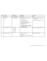
Page 7: ...3 16 10 9 11 12 13 15 4 18 17 19 20 21 22 D12244 1 SMARTP P I IL L O OT T 14 The display uses a number of protocols to transfer data between the various devices in your system The following table det...

Page 8: ...iPhone 4 or later or iPad requires the Raymarine Viewer video streaming app available from the Apple App Store Chartplotter sync with Navionics Marine app WiFi Video streaming WiFi Media player contro...

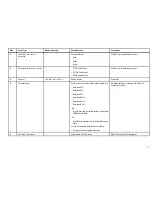
Page 9: ...i70 SeaTalk SeaTalkng 5 Instruments third party Connections to multifunction display NMEA outputs 4 Connections to multifunction display NMEA inputs 2 NMEA 0183 compatible instruments NMEA 0183 6 Pilo...

Page 10: ...ng or NMEA 0183 8 AIS third party 1 Third party NMEA 0183 compatible AIS Class A or Class B receiver transceiver NMEA 0183 9 Vessel trim tabs third party 1 pair Third party NMEA 2000 interfaces NMEA 2...

Page 11: ...Component 15 Sonar transducer 1 Direct connection to display Sonar variant displays only Raymarine P48 Raymarine P58 Raymarine P74 Raymarine B60 20 Raymarine B60 12 Raymarine B744V OR Any 600 watt 1Kw...

Page 12: ...ditional multifunction display s third party Connections to multifunction display NMEA outputs 4 Connections to multifunction display NMEA inputs 2 NMEA 0183 compatible chartplotters and multifunction...

Page 13: ...ch may damage the structure of the vessel Cable entry Ensure the unit is mounted in a location which allows proper routing and connection of cables Minimum bend radius of 100 mm 3 94 in unless otherwi...

Page 14: ...the maximum possible distance between the display and any compasses Typically this distance should be at least 1 m 3 ft in all directions However for some smaller vessels it may not be possible to lo...

Page 15: ...tely removed from the display Flush mounting You can mount the display in a flush or panel mounting arrangement Before mounting the unit ensure that you have Selected a suitable location Identified th...

Page 16: ...to the display Bracket trunnion mounting The display can be mounted on a bracket Before mounting the unit ensure that you have Selected a suitable location Identified the cable connections and route...

Page 17: ...front bezel Before proceeding ensure the memory card slot door is open D12275 1 2 1 2 1 Important Use care when removing the bezel Do not use any tools to lever the bezel doing so may cause damage 1 P...

Page 18: ...isplay variants are listed below D12249 3 e7 e7D e95 e125 e97 e127 c95 c125 c97 c127 Transducer SeaTalkng SeaTalkhs RayNet Network 1 SeaTalkhs RayNet Network 2 Video in out Power Video NMEA 0183 e7 e7...

Page 19: ...Before applying power to this product ensure it has been correctly grounded in accordance with the instructions in this guide Grounding Dedicated drain wire The power cable supplied with this product...

Page 20: ...The suitable fuse rating for the thermal breaker is dependent on the number of devices you are connecting If in doubt consult an authorised Raymarine dealer NMEA 0183 connection D12266 2 6 1 2 3 4 5...

Page 21: ...made whilst in Simulator mode are NOT transmitted to other equipment Enabling simulator mode With the homescreen displayed 1 Select Set Up 2 Select System Settings 3 Select Simulator Homescreen overvi...

Page 22: ...stomize menu options are displayed 5 Select the appropriate page layout for example Splitscreen 6 Select the application s you want to display on the page either by selecting the relevant menu item or...

Page 23: ...uations such as rough sea conditions when it is not appropriate to use the touchscreen In these situations Raymarine strongly recommends that you activate the touch lock and use the physical keys to o...

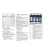
Page 24: ...en item Description 1 Home select this icon to access the homescreen 2 Databar provides information about your vessel and its environment The position and type of information in the databar can be cus...

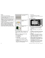
Page 25: ...alarm is cancelled MOB data is removed from the relevant applications The chart application motion mode is reset The chart is centered on the vessel and pitch rotation set to default GOTO and route f...

Page 26: ...3 Tablet smartphone 4 Navionics Marine app To use this feature you must first Download and install the Navionics Marine app available from the relevant app store Enable Wi Fi in the System Settings o...

Page 27: ......

Page 28: ...www raymarine com...

Reviews: