Note:
The appropriate torque to use when drilling
depends on the thickness of the mounting surface
and the type of material.
Note:
The supplied gasket provides a seal between
the unit and a suitably flat and stiff mounting surface
or binnacle. The gasket should be used in all
installations. It may also be necessary to use a
marine-grade sealant if the mounting surface or
binnacle is not entirely flat and stiff or has a rough
surface finish.
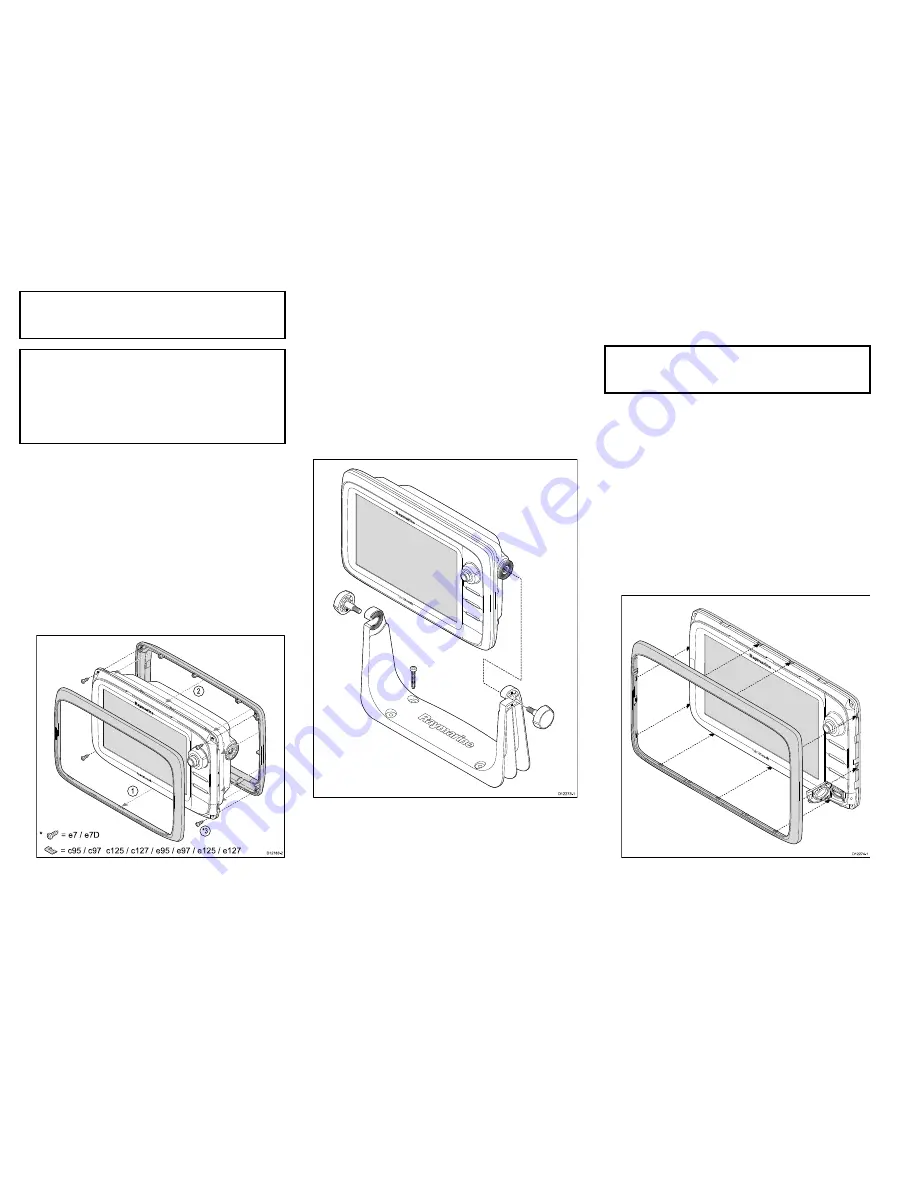
Attaching the rear bezel
The rear bezel must be fitted before mounting the unit
on the supplied trunnion bracket.
1. Remove the front bezel. Refer to the separate
instructions provided for that procedure.
2. Place the bezel over the rear of the display, ensuring
that it is correctly aligned with the display. Apply firm
but even pressure to the bezel along the:
i.
Outer edges - work from the sides upwards and
then along the top edge, to ensure that it clips
securely into position.
ii. Inner edges - ensure that the bezel sits flat
against the unit.
D
12183-2
*
= e 7 / e 7D
=
c95 / c97 c125 / c127 / e 95 / e 97 / e 125 / e 127
*
3
2
1
3. Use the supplied screws to secure the bezel to the
display.
Bracket (trunnion) mounting
The display can be mounted on
a
bracket.
Before mounting the unit ensure that you have:
• Selected a suitable location.
• Identified the cable connections and route that the
cables will take.
• Attach the front bezel.
D
12273-1
1. Mark the location of the mounting bracket screw
holes on the chosen mounting surface.
2. Drill holes for the screws using a suitable drill,
ensuring there is nothing behind the surface that
may be damaged.
3. Use the supplied screws to attach the mounting
bracket securely.
4. Attach the display unit to the mounting bracket.
Note:
The appropriate torque to use when drilling
depends on the thickness of the mounting surface
and the type of material.
Front bezel
Attaching the front bezel
The following procedure assumes that the unit has
already been mounted in position.
1. Carefully lift one edge of the screen protection
film, so that it is accessible for removing when unit
installation is complete.
2. Ensure the memory card slot door is in the open
position.
3. Orientate the bottom-right side of the bezel under the
lip of the chart card door and place the bezel over
the front of the display, ensuring that the clips along
the bottom edge of the bezel latch into position.
D
12274-1
16
e7 / e7D / e95 / e97 / e125 / e127 / c95 / c97 / c125 / c127


