RG27/35/37 Operation • Service • Maintenance
38
Hydraulic Oil - Check
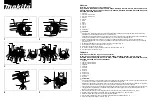
The hydraulic oil tank (1) (reservoir) is the smaller tank directly
behind the larger tank. The oil level is determined either by
pulling out the dipstick, which is part of the oil filter assembly
on top of the reservoir, or by a visual check. The oil level
should be 1” to 1-1/2” from the top of the reservoir. Add oil
if it is below the level indicated.
Check the oil level only when the engine is cold, and with
the machine on level ground.
Re-fill the hydraulic oil tank (1)
1. Clean all surrounding debris and dirt off of the tank fill
opening area. (Hydraulic fluid must be kept completely
clean!)
2. Unscrew the filter cap and pull out the filter.
A 10 micron filter is used on this machine. It is located
in the reservoir. The oild filter head has a built-in relief
, which can open and bypass th egilter if the oil is
extrememly cold or if the filter becomes clogged. It also
has a service indicator that shows when the filter needs
replaced.
3. Fill the tank until the oil level shows 6 to 7” from the
bottom of the dipstick.
4. Replace the filter and cap.
Changing Hydraulic Oil
Drain the Oil
1. Steam clean the pump, motor, cylinders, hydraulic lines,
fittings, and tank.
2. Place the machine on level ground.
3. Place a container below the hose and fitting located
underneath the hydraulic pump.
4. Remove the hose from the fitting and allow the oil to
drain into the container.
5. Clean and install the hose.
6. Loosen the hose fittings on the cylinders, and drain as
much fluid as feasible.
7. Replace and tighten fittings.
8. Dispose of drained oil according to local environment
protection regulations.
Start Up Procedure
1. Make sure all fittings are tight.
2. Fill the reservoir with the recommended hydrau lic oil (see
“Lubrication and Fluid Specifications”), which should be
passed through a 10 micron (nom i nal) non-bypass filter
prior to entering the reservoir. Never reuse fluid.
3. Crank the engine, using the starter, for a short period
of time. This allows the system to begin filling with fluid.
Start the engine and run at the lowest possible speed.
Shut down the engine within 40 seconds if the pump or
motor begin making an unusual noise, indicating a lack
of oil, and be sure the reservoir is full and all the hoses
are properly connected.
4. Set the engine throttle at approximately 50% of maximum
throttle for a few minutes. This will purge trapped air from
the pump/control valve cir cuit.
5. Cycle the self-propel drive lever, two or three times,
to purge all remaining trapped air from the self-propel
motor circuit.
The hydraulic motor is now ready for operation.
6. Now the hydraulic cylinders circuits may be prepared.
Run the engine at normal operating speed. Using
the cutting boom motion lever, slowly, then at normal
operating speed, cycle the cylinders through all their
motions until all the air is bled off. The motions will be
smooth and powerful when all of the air is bled off.
7. Check the reservoir level, and add more clean fluid if
necessary.
The hydraulic system is now completely ready for
operation.
8. Clean up any spilled hydraulic fluid.
NOTICE
Replace oil if it smells burnt or appears to be dirty.
Use only clean, fresh hyrdaulic oil, free of bubbles.
(Bubbles indicate trapped air.)
2
1
NOTICE
Keep the interior of all hydraulic components
clean as they are installed. The machine must not
be operated without the filter in place, or sever
damage to the major hydraulic compnents will
likely occur.
NOTICE
Prior to filling with fluid, make certain all system
components (reservoir, hoses, valves, fit
tings,
pump, etc.) are clean. Care must be taken to not run
the pump or hydraulic motor without a sufficient
amount of flu id in them.
Maintenance
Summary of Contents for Super Jr RG27
Page 47: ...RG27 35 37 Operation Service Maintenance 800 392 2686 47 Maintenance Notes ...
Page 50: ...RG27 35 37 Operation Service Maintenance 50 Wiring Schematic ...
Page 51: ...RG27 35 37 Operation Service Maintenance 800 392 2686 51 Wiring Schematic ...
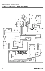
Page 54: ...RG27 35 37 Operation Service Maintenance 54 Hydraulic Schematic RG37 802846 RF T T P P ...
Page 56: ...RG27 35 37 Operation Service Maintenance 56 Specifications SERVICING TAPER BUSHINGS ...
Page 63: ...RG27 35 37 Operation Service Maintenance 800 392 2686 63 ...


