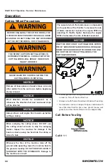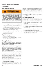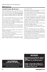
RG27/35/37 Operation • Service • Maintenance
800.392.2686
43
• The belt should deflect 1/2” when 12-15 lbs. force is
applied.
• Use 12 lbs. at 1/2” deflection when installing a new
belt. After approximately 5-10 hours it will begin to seat
in and drop down into the 12-15 lbs. range at 1/2”
deflection. If the tension is acceptable, ignore steps
2-7. If the tension is too low, follow steps 2-7.
2. Loosen the two bolts (6) holding each bearing, enough
to allow the bearings to slide easily.
3. Loosen the lock nuts (7) on the two bearing jacking
screws (8) & (5).
4. Back-off the jacking screw (8) one full turn.
5. Tighten the jacking screw (9) one full turn.
6. Check the PolyChain® tension. If more tension is nec-
es sary, repeat steps 4 and 5, and recheck the tension.
7. When the tension is cor rect, tighten the bearing bolts
and jacking screw lock nuts, and reinstall the PolyChain®
guard.
8. Check after 10 hours run time, and adjust if needed.
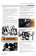
Jackshaft V-Belt - Check & Adjust
Tension
1. Remove the belt guard cover.
2. Plunger Gage. The belt tension should be set to deflect
1/2” using 18-20 lbs force with a belt plunger gage.
If tension is acceptable, proceed to step 7.
3. Loosen the four engine mounting bolts (10) which secure
the engine to the cutting boom.
4. Loosen the jam nut (11) on the engine adjusting nut.
Turn the engine adjusting nut (12) clockwise to tighten
the belts to the proper tension.
5. Check the belt tension again. If it is too loose, repeat
step 4 and check again until it is properly set.
6. Retighten the engine bolts and locknut.
7. Replace the belt guard cover.
Hydraulic Pump Belt - Check &
Adjust Tension
With the pump guard removed, deflect the belt at midway of the
span, using firm hand pressure. It should deflect approximately
1/8” with 8-10 lbs force when properly tensioned.
To Adjust Belt Tension:
1. Remove the pump guard and sheave guard.
2. Loosen the four pump bracket bolts (1).
3. To tighten the belt, tighten the adjusting screw (2).
4. Check the tension, and repeat until the proper tension
is obtained.
5. Re-tighten the four pump bracket bolts (1).
6. Re-mount the pump guard and sheave guard. Firmly
tighten all screws.
Maintenance
6
8
9
7
THE MACHINE MUST BE SHUT DOWN WHEN
CHECKING AND ADJUSTING BELT TENSION.
10
11
12
Summary of Contents for Super Jr RG27
Page 47: ...RG27 35 37 Operation Service Maintenance 800 392 2686 47 Maintenance Notes ...
Page 50: ...RG27 35 37 Operation Service Maintenance 50 Wiring Schematic ...
Page 51: ...RG27 35 37 Operation Service Maintenance 800 392 2686 51 Wiring Schematic ...
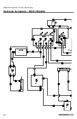
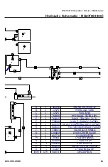
Page 54: ...RG27 35 37 Operation Service Maintenance 54 Hydraulic Schematic RG37 802846 RF T T P P ...
Page 56: ...RG27 35 37 Operation Service Maintenance 56 Specifications SERVICING TAPER BUSHINGS ...
Page 63: ...RG27 35 37 Operation Service Maintenance 800 392 2686 63 ...


