www.raycap.com
©Raycap • All rights reserved
320-1204 Rev.E
Page 15 of 38
INSTALL INSTRUCTIONS
RCMDC-6627-PF-48
11.5
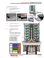
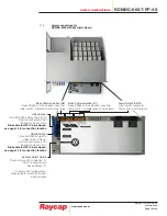
Alarm connections for
RCMDC-4520-RM-48x Alarm Board
Alarm Output to BTS
(dry contact outputs for
Power, H
2
O, and Intrusion)
Base Communication (D2)
Base RS485 communication input from
tower top #2, 2-twisted pair (4 wires total)
Base Communication (D1)
Base RS485 communication input from
tower top #1, 2-twisted pair (4 wires total)
Address Select Switch
Place rotary switch to position “0”
which corresponds to
base address “0”
If in daisy chain configuration,
place selector switch to the next
base address
VBoost Input
Optional RS485 daisy chain input.
Remote connection point
located on back of unit.
Blue cable is NOT to be removed,
see page 14 for connection location
VBoost Output
Optional RS485 output to
daisy chain / VBoost.
Remote connection point
located on back of unit.
Blue cable is NOT to be removed,
see page 14 for connection location


