background image

www.raycap.com

©Raycap  •  All rights reserved

320-1204  Rev.E

Page 11 of 38


INSTALL INSTRUCTIONS      

RCMDC-6627-PF-48

Installing Ground Cable

10.1


There are two grounding placement


options available. See below.

Optional Cable Grounds

Main Ground

Hybrid Trunk 

Ground Points

Summary of Contents for RCMDC-6627-PF-48

Page 1: ...Installation Instructions RCMDC 6627 PF 48 INSTALL INSTRUCTIONS RCMDC 6627 PF 48 www raycap com ...

Page 2: ......

Page 3: ...on 4 4 Procedure 5 4 1 Mounting Procedures 5 5 1 Gland Insert Definitions 5 6 1 Pre wiring Preparation Procedure 6 7 1 Cable Installation Instructions 8 8 1 Installing Hybrid Cable Power In 9 9 1 Installing Hybrid Jumper Cable Power Out 10 10 1 Installing Ground Cable 11 11 1 Alarm Wiring 12 12 1 Installing Hybrid Cable Fiber In 24 13 1 Installing Hybrid Cable Fiber Out 25 14 1 Installation Comple...

Page 4: ...instructions and cautionary markings on the product and on any equipment connected to the product CAUTION Unless otherwise noted product usage that is not recommended or sold by the product manufacturer can result in risk of fire electric shock or injury to persons CAUTION Do not operate the product if it has been damaged in any way Return damaged products to their manufacturer for repair or repla...

Page 5: ...o withstand direct lightning currents in order to protect the sensitive equipment Raycap s RRH solutions featuring Strikesorb SPD technology significantly enhance the reliability availability of the RRH site by providing superior electrical protection at the RRH and BBU and also enable flexible fiber optic and power cable management solutions 3 0 Overvoltage Protection Package Contents One 1 Enclo...

Page 6: ... properly to the newly installed 6627 Whenever installing a 6627 at the tower top the alarm board rotary switch should be in the default 1 position Any unit installed at the base connected to a 6627 at the top whether it be a 4520 2260 retrofit 3315 retrofit or another 6627 will be at rotary switch position 2 If there are subsequent units daisy chained at the base they will take the next number on...

Page 7: ...tainless steel bands not supplied through slots on bracket to mount to Monopole Gland Insert Definitions 5 1 See picture to identify Base Gland Assembly Definitions Assembled in unit as shipped Qty Connector Size Pos Insert P N Insert Hole Cable Type 2 M75 A 190 0760 42mm 6x12 RL 4 M75 B 190 0738 3x 16 5mm 1x2 Included in kit shipped with unit Qty Connector Size Insert P N Insert Hole Cable Type P...

Page 8: ...l rights reserved 320 1204 Rev E Page 6 of 38 Pre wiring Preparation Procedure 6 1 Ensure the lanyard from enclosure lid to enclosure base is secure 6 2 Open up clamps on all sides of the enclosure cabinet by lifting the hinged clamp tabs 6 3 Remove enclosure lid ...

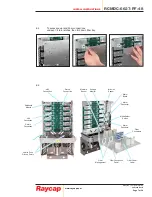
Page 9: ...unclasp 1 4 turn latches then fold down fiber tray 6 5 Return Connection Fiber Connection Panel Fiber Management Fiber Connectors Fiber Panel Label Alarm Board Alarm Connector Alarm Connector Mode Select Switch Moisture Sensor Intrusion Sensor Strikesorb Module 48V Connection Voltage Monitor Return Connection Hybrid Trunk Ground Points 48V Connection ...

Page 10: ...the enclosure The following steps will show how to install the Hybrid cable properly 7 2 Remove compression nut 7 3 Remove center insert from cable gland 7 4 Slide compression nut and insert over the cable breakout Be careful not to damage the fiber connectors Insert needs to be 1 behind heat shrink tube 7 5 Carefully feed fiber and power conductors into the OVP box and tighten the compression nut...

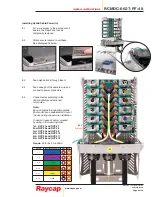
Page 11: ...ect to power connectors 8 5 Connect wires according to the Verizon Wireless established color guide Note Bring all cables through cable glands Ensure all fiber is separated and out of the way during copper wire installation To assist in ease of wiring proceed by wiring in the following order 1st OVP 1 and OVP 7 2nd OVP 2 and OVP 8 3rd OVP 3 and OVP 9 4th OVP 4 and OVP 10 5th OVP 5 and OVP 11 6th O...

Page 12: ...nnectors 1 7 2 8 3 9 4 10 5 11 6 12 1 7 2 8 3 9 4 10 5 11 6 12 9 3 Connect wires according to the Verizon Wireless established color guide Note To assist in ease of wiring proceed by wiring in the following order 1st OVP 1 and OVP 7 2nd OVP 2 and OVP 8 3rd OVP 3 and OVP 9 4th OVP 4 and OVP 10 5th OVP 5 and OVP 11 6th OVP 6 and OVP 12 Torque 40 in lbs 10 6 AWG Jumpers 1 6 installed Hybrid Trunk not...

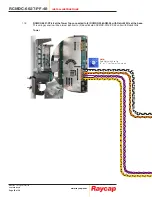
Page 13: ...ts reserved 320 1204 Rev E Page 11 of 38 INSTALL INSTRUCTIONS RCMDC 6627 PF 48 Installing Ground Cable 10 1 There are two grounding placement options available See below Optional Cable Grounds Main Ground Hybrid Trunk Ground Points ...

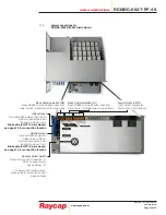
Page 14: ...ch Base mode operation Place rotary switch to position 2 which corresponds to base mode address 0 If in daisy chain configuration place selector switch to the next base mode address Tower Communication D2 Tower Top RS485 communication output to base 2 twisted pair 4 wires total Base Communication D2 Base RS485 communication input from tower 2 twisted pair 4 wires total VBoost Input not used in Tow...

Page 15: ...2 L2 U9 L9 UA LA Ub Lb UC LC During normal operation the display will show the voltage of selected circuit Top Unit The top unit will only display its own status Reverse Polarity Short Circuit Low Voltage less than 35V Left Dot Blinking receiving daisy chain data Right Dot Blinking receiving tower top data Tower Top Unit both dots blink indicating transmission Circuit status messages Base Unit Tow...

Page 16: ...trusion Base Communication D2 Base RS485 communication input from tower 2 twisted pair 4 wires total Mode Select Switch Base mode operation Place rotary switch to position 2 which corresponds to base mode address 0 If in daisy chain configuration place selector switch to the next base mode address VBoost Input Optional ethernet daisy chain input VBoost Output Optional ethernet output to daisy chai...

Page 17: ...mmunication input from tower top 1 2 twisted pair 4 wires total Address Select Switch Place rotary switch to position 0 which corresponds to base address 0 If in daisy chain configuration place selector switch to the next base address VBoost Input Optional RS485 daisy chain input Remote connection point located on back of unit Blue cable is NOT to be removed see page 14 for connection location VBo...

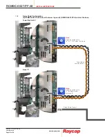
Page 18: ...rved 320 1204 Rev E Page 16 of 38 Note Selector switch set to or 1 for Tower Top mode Note Selector switch set to 0 for Base address 0 Alarm Outputs to BTS 11 6 Standard Base Tower Configuration 1 RCMDC 6627 PF 48 unit at the tower top and 1 RCMDC 4520 RM 48x unit at the base ...

Page 19: ...Outputs to BTS Tower Base communication Note Selector switch set to or 1 for Tower Top mode Note Selector switch set to 2 for Base mode address 0 Optional Output to VBOOST Tower Top Unit Base Unit 11 7 Standard Base Tower Configuration 1 RCMDC 6627 PF 48 unit at the tower top and 1 RCMDC 6627 PF 48 unit at the base ...

Page 20: ...ge 18 of 38 Tower Base communication Note Selector switch set to or 1 for Tower Top mode Note Selector switch set to 2 for Base mode address 0 Daisy Chain Output 11 8 Daisy Chain Configuration 2 RCMDC 6627 PF 48 units at the tower top and 2 RCMDC 6627 PF 48 units at the base Tower Top Unit 1 Base 0 ...

Page 21: ...8 INSTALL INSTRUCTIONS RCMDC 6627 PF 48 Alarm Outputs to BTS Daisy Chain Output to next Base unit Tower Base communication Note Selector switch set to or 1 for Tower Top mode Note Selector switch set to 3 for Base mode address 1 Daisy Chain Input Tower Top Unit 2 Base 1 ...

Page 22: ...04 Rev E Page 20 of 38 Note Selector switch set to or 1 for Tower Top mode 11 9 RCMDC 6627 PF 48 at the Tower Top connected to 2 RCMDC 2260 RM 48 with Retrofit Kits at the base This wiring scenario will be almost identical to 2 base located RCMDC 3315 PF 48 units with Retrofit Kits Tower ...

Page 23: ...ev E Page 21 of 38 INSTALL INSTRUCTIONS RCMDC 6627 PF 48 Alarm Outputs to BTS Note Selector switch set to 3 for Base mode address 1 Note Selector switch set to 2 for Base mode address 0 Daisy Chain Output to next Base unit Daisy Chain Input Base 0 Base 1 ...

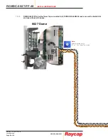
Page 24: ...com Raycap All rights reserved 320 1204 Rev E Page 22 of 38 6627 Dome Note Selector switch set to or 1 for Tower Top mode 11 10 RCMDC 6627 PF 48 at the Tower Top connected to 2 RCMDC 2260 RM 48 racks one with a Retrofit Kit and one without at the base ...

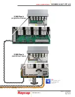
Page 25: ... All rights reserved 320 1204 Rev E Page 23 of 38 INSTALL INSTRUCTIONS RCMDC 6627 PF 48 Alarm Outputs to BTS 2260 Rack Original Alarm Board 2260 Rack Retrofit Alarm Board Note Selector switch set to 2 for Base mode address 0 ...

Page 26: ...Remove the plugs in the fiber connectors to be used To avoid contamination do not remove any plugs until fiber is immediately ready to be installed Example pull one plug plug in fiber repeat 12 3 Connect the cables into the fiber connection panel starting with the row closest to the back plate and feed through the cable guides 12 4 Connect fiber according to the Verizon Wireless established guide ...

Page 27: ...ll be used To avoid contamination do not remove any plugs until fiber is immediately ready to be installed Example pull one plug plug in fiber then do the next one repeat Note Always keep un used connectors plugged 13 3 Connect the cables into the fiber connection bar starting with the row closest to the back plate and feed through the cable guides as shown 13 4 Connect fiber according to the Veri...

Page 28: ...RCMDC 6627 PF 48 INSTALL INSTRUCTIONS www raycap com Raycap All rights reserved 320 1204 Rev E Page 26 of 38 Installation Complete Installed cable routing examples ...

Page 29: ...CTIONS RCMDC 6627 PF 48 Installation Complete Closing and Securing Unit 14 1 Slide enclosure lid into place Red must be completely covered for proper lid alignment 14 2 If installation requires padlocks not provided secure bottom right enclosure 14 3 As pictured Lid IS properly aligned ...

Page 30: ...ase Unit Connected at Top Configuration Supported Base Unit 1 Tower 1 Tower 2 6627 6627 NONE YES 6627 3315 with Retrofit NONE YES 6627 3315 with Retrofit 3315 with Retrofit YES 6627 6627 6627 NO 6627 6627 3315 NO 6627 12 OVP Dome 3315 6 OVP Dome with Retrofit Retrofit Alarm Board installed 6 OVP Rack Dome Configurations Base Unit Connected at Base Unit Connected at Top Configuration Supported Base...

Page 31: ...www raycap com Raycap All rights reserved 320 1204 Rev E Page 29 of 38 INSTALL INSTRUCTIONS RCMDC 6627 PF 48 Addendum High Power Wire Bridge Kit Optional For Model RCMDC 6627 PF 48 ...

Page 32: ...e no liability for any error damage of any kind resulting from the use of this document A 1 2 Prerequisites This document describes how to install the High Power Wire Bridge Kit on site and how to mount and connect it to external interfaces Installers of Raycap s RRH surge protective and fiber power management solutions must be industry professionals who have attended training on the proper instal...

Page 33: ...1 Remove 4 set screws A 2 2 Install 4 custom set screws Allow room for wire install under lug Install 48V and RTN cables Tighten custom lug set screws securing input cables using 1 2 nut driver A 2 3 Install 48V jumper wire between first and second OVP with kep nut using 7 16 socket Install RTN jumper wire between first and second OVP with kep nut using 7 16 socket 48V RTN ...

Page 34: ...ap All rights reserved 320 1204 Rev E Page 32 of 38 Insulator Caps A 2 4 Install 4 insulator caps over custom installed lugs A 2 5 Remaining 4 lugs ready for high power radio installation A 2 6 Installation complete connecting 2 circuits for high power radios ...

Page 35: ...www raycap com Raycap All rights reserved 320 1204 Rev E Page 33 of 38 INSTALL INSTRUCTIONS RCMDC 6627 PF 48 Vertical Installation Completed A 2 7 Completed Wiring example See below ...

Page 36: ... 1 Remove 4 set screws A 3 2 Install 4 custom set screws Allow room for wire install under lug Install 48V and RTN cables Tighten custom lug set screws securing input cables using 1 2 nut driver A 3 3 Install 48V jumper wire between first and second OVP with kep nut using 7 16 socket Install RTN jumper wire between first and second OVP with kep nut using 7 16 socket 48V RTN ...

Page 37: ...Page 35 of 38 INSTALL INSTRUCTIONS RCMDC 6627 PF 48 Insulator Caps A 3 4 Install 4 insulator caps over custom installed lugs A 3 5 Remaining 4 lugs ready for high power radio installation A 3 6 Installation complete connecting 2 circuits for high power radios ...

Page 38: ...RCMDC 6627 PF 48 INSTALL INSTRUCTIONS www raycap com Raycap All rights reserved 320 1204 Rev E Page 36 of 38 Horizontal Installation Completed A 3 7 Completed Wiring example See below ...

Page 39: ......

Page 40: ...RCMDC 6627 PF 48 INSTALL INSTRUCTIONS www raycap com Raycap All rights reserved 320 1204 Rev E Page 38 of 38 ...

Reviews: