RCMDC-6627-PF-48
INSTALL INSTRUCTIONS
www.raycap.com
©Raycap • All rights reserved
320-1204 Rev.E
Page 12 of 38
11.0
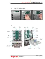
Alarm connections for RCMDC-6627-PF-48
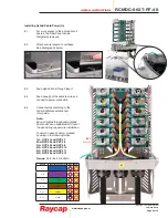
11.1
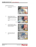
Installing Alarm Wiring for RCMDC-6627-PF-48
Tower Top
Configuration
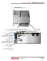
11.2
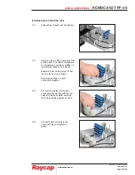
Installing Alarm Wiring for RCMDC-6627-PF-48
Base
Configuration
Alarm Output to BTS
(not used in Tower Top Configuration)
Alarm Output to BTS
(dry contact outputs for Intrusion, H
2
O, and Power)
Rotary Switch
(
·
)
& 1 are identical in functionality, therefore
either may be selected for tower top mode
Rotary Switch
Base mode operation. Place rotary switch to position “2”
which corresponds to base mode address “0”
If in daisy chain configuration, place selector switch to
the next base mode address
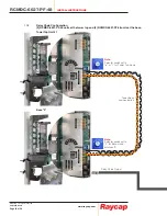
Tower Communication (D2)
Tower Top RS485 communication output to base,
2-twisted pair (4 wires total)
Base Communication (D2)
Base RS485 communication input from tower, 2-twisted pair
(4 wires total)
VBoost Input
(not used in Tower Top Configuration)
VBoost Input
Optional ethernet daisy chain input
VBoost Output
(not used in Tower Top Configuration)
VBoost Output
Optional ethernet output to daisy chain / VBoost
Tower Communication (D1):
Tower Top RS485 communication output to base,
2-twisted pair (4 wires total)
Base Communication (D1):
Optional RS485 daisy chain input


