ray 200i Installation And Operation Instructions Manual Download Page 26

26

P/N 42-9470 11/07 Copyright 2007 Mestek, Inc.

Cast iron condensing boiler


Cast iron condensing boiler

 — Installation and operation manual

Control setup 

(continued)

8

Recommended settings

Th e following recommendations should cover most single-boiler applications.
Th

 e sett ings covered in this manual are SETPOINTS, INDOOR AIR, OUTDOOR 

AIR and SYSTEM CLOCK.
For other sett ings and a complete menu tree, consult the 

200i

 Control manual for 

information.

Adjust SETPOINTS 

Setpoint menus

Use the arrow keys until the cursor points at SETPOINTS.
Press the SELECT butt on to enter the SETPOINTS menus. Th e menu selections 
available as you use the arrow keys will be:

LOC SETPOINT

 (means the local setpoint, or the target temperature of the 

boiler supply water; this is sensed by the SUPPLY sensor).

SOURCE

 (means whether the setpoint temperature is to be controlled at the 

boiler or by a remote device — leave the default sett ing of AUTO unless you 
plan to use a remote controller with a 4-20ma output).

DHW SETPOINT

 (means the supply temperature the boiler will target when 

operating on a call for DHW heating; this uses the same sensor as the local 
setpoint).

OP LIMIT

 (means the operating limit temperature of the boiler).

LIMIT BAND

 (this is the diff erential for the limit function).

Set the local setpoint (LOC SETPT)

Use the arrow keys until the cursor points at LOC SETPT. Th e display will show:

2. Th e cursor must be pointing at LOC SETPT. Th e value shown may vary if the con-

trol has been adjusted before.

3.  Press the SELECT butt on to change the local setpoint value.
4. Th e cursor will move to the temperature number.
5.  Use the arrow keys to increase or decrease the temperature to the desired sett ing.

  If you hold down the arrow key the numbers will change faster aft er a 

brief waiting period.

6. When 

the 

sett ing is correct, press the SELECT key to accept. Th en press the BACK 

key to leave the local setpoint adjustment.

7. Th e local setpoint should be set at the design water temperature for the heating 

units (typically 180°F for fi nned-tube baseboard, for example).

  Th e setpoint must never be higher than the OP LIMIT sett ing minus 

the LIMIT BAND minus half of the HEAT BAND sett ing. Th is would 
cause the boiler to hit limit while trying to modulate.


Example:  If LIMIT BAND is 20°F, OP LIMIT is 215°F, and HEAT 
BAND is 30°F, the local setpoint must never be higher than 215 - 20 
- 30/2 = 180°F.

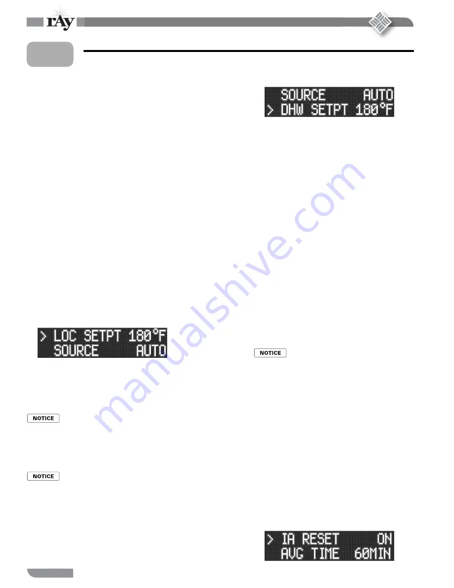
Set the DHW setpoint (DHW SETPT)

Skip this procedure if the boiler is not used for DHW heating.
Use the arrow keys until the cursor is at DHW SETPT. Th e display will be:

1.
2.

3.

1.
2.


1.

1.
2.

3.  With the cursor on DHW SETPT, press the SELECT key 

to change the value, using the same procedure as with the 
LOC SETPT adjustment.

4. Th e DHW setpoint should usually be 190°F. To obtain this 

setpoint, you will also have to increase the OP LIMIT set-
ting to 225 or 230°F so the boiler won’t prematurely cycle 
on the limit function.

5.  When the DHW sett ing is complete, press SELECT and 

BACK to return to the setpoint menus.

Set OP LIMIT (operating limit)

Use the same procedure as on the previous sett ings  to 
change the operating limit temperature.
Use the arrow keys to select OP LIMIT, then press SELECT.
If the boiler setpoint is to be higher than 180°F, you will 
need to increase OP LIMIT. Th e maximum sett ing for OP 
LIMIT is 230°F. So the maximum allowable boiler setpoint 
is generally 190°F.
Once the sett ing is correct, press SELECT, then BACK to 
return to the setpoint menus.

The LIMIT BAND

Do not change the LIMIT BAND sett ing unless specifi c 
application demands require a change or when directed by 
the factory.

Return to main menus

  When the setpoints have all been adjusted as 

desired, press the BACK key until you return to 
SETPOINTS.

INDOOR AIR

General

Use the indoor air reset option whenever possible. Th e 
indoor air technology monitors space heating demand to 
help the boiler operate at the highest possible effi  ciency 
throughout the season.
To apply indoor reset you must wire the IAR inputs and the 
HEAT DEMAND terminals as described in Section 7.

Enable or disable IAR

Th e only sett ing for indoor air reset that you will need to 
make is to enable the function.
Use the arrow keys until the cursor points to 

INDOOR AIR

.

Press SELECT to enter the indoor air menus.
Th e display will show:

1.

2.
3.

4.

1.

1.

2.
3.
4.

Summary of Contents for 200i

Page 1: ...ated with a dust freeairsupply Followtheinstructionmanualprocedurestoductairtotheboilerairintake Iftheboilerhasbeencontaminatedbyoperation with contaminated air follow the instruction manual guideline...

Page 2: ...ication sensing Because of its low excess air operation and controlled combustion the burner also provides low NOX emissions and quiet operation Gas valve blower and venturi Most gas valves regulate a...

Page 3: ...mbly Pressure switches blocked flue and blocked air inlet Control connection board Electrical box power and control entrances Water return connection Air inlet sleeve Relief valve Relief valve piping...

Page 4: ...ore leaving the installation site after start or service fill out the Start up service history information on the back page Contents Customer service and technical support Please direct all questions...

Page 5: ...s Should overheating occur Do not shut off power to the circulators if the boiler should overheat or thegassupplyfailtoshutoff Instead shutoffgassupplytotheboilerwith a manual valve in the gas supply...

Page 6: ...ctrical requirements Voltage 120 vac 60 hz 1 phase Current draw 120 volt power line Amperes 2 75 Thermostat anticipator setting Amperes 0 5 Operating control Mestek SmartCycleTM control 4 Control oper...

Page 7: ...duct or other means of providing make up air if the intake air op tion isn t used Any building utilizing other gas burning ap pliances a fireplace wood stove or any type of exhaust fan must be checke...

Page 8: ...ftheboilerroom provides at least the minimum SERVICE OPERATION clearances given in Table 2 Failure to provide adequate ventilation could result in overheating of the boiler components or the room pote...

Page 9: ...dings as having all of the following Walls and ceilings exposed to the outside atmosphere have a continuous watervaporretarderwitharatingof1permorlesswithopeningsgasketed Weather stripping has been ad...

Page 10: ...losion causing possible severe personal injury death or substantial property damage Connecting the relief valve Connect inch NPT black iron pipe and fitting so the relief valve as shown in Figure 4 Fo...

Page 11: ...a section of the piping that will ensure enough flow to operate the switch Additional high limit controls For ASME CSD 1 or Canadian applications or when required by applicable codes install an additi...

Page 12: ...those that have air above the water in direct contact with the water See Figure 5 right side See Figure 7 for suggested piping Guidelines for closed type expansion tanks NEVER use automatic air vents...

Page 13: ...d 12 Extra high limit when required 13 Zone valve 14 Zone circulator 15 Differential pressure by pass valve Use when high head circulator may cause noise erosion or valve lifting problems when only a...

Page 14: ...tion of DHW tanks Makesuretoincorporateflow checkvalvesasshown Thesepreventforced flow in idle zones LEGEND 1 200i boiler 2 Boiler circulator 4 Boiler system circulator 5 Indirect fired DHW tank when...

Page 15: ...through the heating loop s This is important for summer time operation of DHW tanks Makesuretoincorporateflow checkvalvesasshown Thesepreventforced flow in idle zones LEGEND 1 200i boiler 2 Boiler ci...

Page 16: ...ation when required When heating system boilers are piped in parallel as in Figure 12 connect the DHW tank as a zone off of the main header or install boilers dedicated to the DHW application LEGEND 1...

Page 17: ...es If using variable speed control of the system circulator ensure that the flow never drops below the total minimum for all boil ers connected The boiler loop can be any of the designs in this manual...

Page 18: ...ock pressure test port Check the gas type The 200i comes from the factory ready to be piped to the gas supply If for any reason the boiler is not for the type of gas avail able at the installation sit...

Page 19: ...ipe sizing Required supply pressure at boiler Minimumgassupplypressure naturalgasorpropane bothfor flowing and static conditions 4 inches 102 mm water column Maximum gas supply pressure natural gas or...

Page 20: ...substantial property damage The electrical connections to this boiler must be made in accordance with all applicable local codes and the latest revision of the National Electrical Code ANSI NFPA 70 In...

Page 21: ...ith the boiler cannot be used for system circulation Itmustbeused assuppliedfromthefactory Itcirculateswateraftertheboiler stops firing to prevent potential damage from heat pocketing in the top of th...

Page 22: ...using 4 wire zone valves without a zone controller For other applications such as circulator relays or zone controllers see Appendix A in this manual Also see the Control manual Polarity The connectio...

Page 23: ...c Cast iron condensing boiler Cast iron condensing boiler Installation and operation manual Figure 21a 200i wiring summary see Boiler manual and Control manual text for additional information Wiring a...

Page 24: ...boiler Cast iron condensing boiler Installation and operation manual Figure 21b 200i wiring summary see Figure 21 for locations see Boiler manual and Control manual text for additional information Wir...

Page 25: ...ff switch ON The control will beep at least twice and the display will show the first STANDBY display in Figure 22 Note that pushing the DOWN button on the keypad will change the right side of the dis...

Page 26: ...xample The setpoint must never be higher than the OP LIMIT setting minus the LIMIT BAND minus half of the HEAT BAND setting This would cause the boiler to hit limit while trying to modulate Example If...

Page 27: ...e arrow keys until the cursor points at OA RESET The default setting is ON To change the setting press SELECT and use the arrow keys to change from ON to OFF Press SELECT then BACK If outdoor reset is...

Page 28: ...ndanyothergas burningappliance to their previous condition of use Any improper operation of the common venting system should be corrected so the installation conforms with the National Fuel Gas Code A...

Page 29: ...l a cover over the tubing or some other means to protect it from damage or movement Prevent freezing Do not route the line through or termi nate the line in any area that could expose the condensate t...

Page 30: ...atter Use cleaning chemicals sold for use in hydronic systems Replacementboilerinstallationsoftenhavelargeamountsofaccumulatedsediment and corrosion that must be removed to ensure boiler life and reli...

Page 31: ...tem water temperature reaches the maximum op erating temperature that the system and boiler temperature controls will allow The pressure in the boiler must never be below 12 psig Lower pressure could...

Page 32: ...smell Before start up and periodi cally afterwards have the propane supplier check verify the odorant level Never attempt to measure gas valve outlet pressure Donotattempttomeasuretheboilergasvalveou...

Page 33: ...sig 3 5 kPa Manual gas valve Open the main manual gas valve and check the gas piping and joints in the boiler Check for leaks if not already done following the instructions on page 18 Starting the boi...

Page 34: ...ow the bottom of the heat band 10 seconds PRE PURGE Ignition trial ON at ignition RPM 30 of maximum 4 seconds ON ON IGN 30 Flame is sensed Stabilization period ON at ignition RPM 30 of maximum 6 secon...

Page 35: ...4 5 Wait five minutes to clear out any gas Then smell for gas including near the floor If you smell gas Follow B in the safety information above If you don t smell gas go to the next step 6 Turn manu...

Page 36: ...36 P N 42 9470 11 07 Copyright 2007 Mestek Inc Cast iron condensing boiler Cast iron condensing boiler Installation and operation manual Illustration 26 En francaise Starting the boiler continued 12...

Page 37: ...p covering the flue gas sam pling hole Figure 27 The flue gas vent pipe may be hot Touching the pipe with unprotected skin could result in a severe burns 2 Slide the hose clamp off of the sample openi...

Page 38: ...he gas pressure at the manual gas valve Gas pressure should never fall off by more than 2 inches w c 50 mm To meter gas input natural gas only Meter gas input with the high fire jumper in place Turn o...

Page 39: ...erlysupported Remove the seven Phillips head screws securing the jacket top to the jacket sides Lift off the jacket top Leave the wire harnesses connected Move the insulation aside if necessary Adjust...

Page 40: ...ration with prepurge then continue through a normal start cycle With the manual gas valve closed the boiler should attempt ignition three times then lockout as described below Ignition failure Make su...

Page 41: ...er is damaged or blocked with debris consult the factory for corrective action Operating the boiler with a damaged or 13 obstructed heat exchanger could result in severe personal injury death or subst...

Page 42: ...afterwardstopre vent contamination of other clothing NIOSH First aid procedures Eye exposure irrigate immediately Breathing fresh air Read before proceeding Failure to adhere to the following could re...

Page 43: ...r 10 Replace the three thumbscrews and finger tighten securely 11 Turn the boiler on off switch ON Accessing the electrode assembly Turn the boiler on off switch OFF If the boiler ignition electrodes...

Page 44: ...of the assembly and a lock washer on top 8 Disconnect the three wire harnesses at the gas valve and blower items 2 and 3 Figure 36 In this illustration the wires are not shown 9 Lifttheuppercoverplate...

Page 45: ...45 P N 42 9470 11 07 Copyright 2007 Mestek Inc Cast iron condensing boiler Cast iron condensing boiler Installation and operation manual Maintenance continued 14 Notes...

Page 46: ...ABS UPPER COVER 1 24 59 1091 FILTER BOX ADAPTER GASKET 1 25 70 1237 FILTER BOX ADAPTER 1 26 57 2913 1 4 20 X 1 NYLOK SC HD CAP SCREW 4 27 54 3234 1 2 FLEX GAS LINE 1 ITEM PARTNo DESCRIPTION QTY 28 70...

Page 47: ...47 P N 42 9470 11 07 Copyright 2007 Mestek Inc Cast iron condensing boiler Cast iron condensing boiler Installation and operation manual Replacement parts continued 15...

Page 48: ...Connectingthewiresincorrectlycancausethe transformer to be shorted out and damaged 3 wirezonevalves Youwillhavetorewireexisting3 wirezonevalves tomeettherequirementsshowninFigure A1 Movethethermostat...

Page 49: ...replace with a circulator zoning controller or install relays that provide a 24VAC common terminal Heat Demand terminal connections using circulator relays The end switch leadsfromtherelaysmustconnect...

Page 50: ...s shown in Figure A3 The connections to the IAR negative terminals IAR must be from the zone controller s 24VAC common terminal as shown Connecting the wires incorrectly can cause the transformer to b...

Page 51: ...densing boiler Installation and operation manual Figure A3 Indoor Air Reset wiring to IAR terminals Heat Demand and DHW Demand using typical zone controller for either circulators or zone valves see F...

Page 52: ...alled correctly Air purged from water system Boiler operated through several cycles Air vents checked and opened as needed Limits and interlocks tested Water piping correct and operational Metered gas...

Reviews: