


2
P/N 42-9470 11/07 Copyright 2007 Mestek, Inc.
Cast iron condensing boiler
Cast iron condensing boiler
— Installation and operation manual
The Mestek
200
i
condensing cast iron boiler
Operation
Overview
Th e
200
i
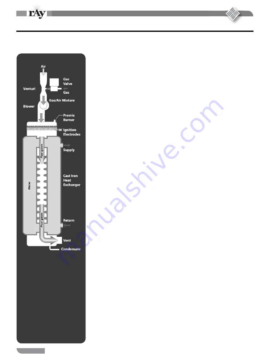
is a cast iron boiler designed and constructed to allow full condensing operation. Th e illustra-
tion at left shows how the boiler is heated with a down-fi red premix gas burner mounted above the heat
exchanger. Th e
200
i
blower pulls gas and air through a venturi assembly and pushes the mixture into the
burner. Th e power of the blower forces the fl ue products through the heat exchanger and out the vent.
Boiler operation is controlled with the
200
i
electronic control. Th e control modulates boiler fi ring rate
based on system demand, allowing input as low as 20% of maximum (5:1 turndown). Combined with
the indoor or outdoor reset option of the
200
i
control, this allows maximum possible condensing mode
operation, with combustion effi ciency up to 98%.
Cast iron heat exchanger
Th
e
200
i
cast iron heat exchanger uses Mestek’s graphite port seals and ground joint fi t-up between sections
for maximum fl exibility and resistance to thermal expansion. Th
e heat exchanger provides maximum
heat transfer with its counterfl ow design and fl ow-controlling baffl e assembly.
Premix burner
Premix means the air and gas are mixed before they enter the burner. Th
e mixing of gas and air in the
blower and piping ahead of the burner causes a uniform gas/air mix in the burner, providing reliable op-
eration with low excess air. Th e result is exceptional combustion effi ciency.
Th e burner consists of a high-temperature stainless mesh secured to a stainless steel distributor plate. Th e
design causes uniform fl ame across the entire surface of the burner and the ability to operate at very low
fi ring rates. Th e fl ame is ignited with direct-spark electrodes and an electronic ignition control. Flame is
proven using a fl ame rod (fl ame rectifi cation sensing).
Because of its low excess air operation and controlled combustion, the burner also provides low NO
X
emissions and quiet operation.
Gas valve, blower and venturi
Most gas valves regulate at a positive pressure downstream of the valve (typically 3½ inches water col-
umn). But the
200
i
gas valve regulates to ZERO pressure downstream. Th is is called a “zero governor”
valve. Th e advantage is that gas will only fl ow if something lowers the pressure downstream of the valve
below zero. Th
at is just what happens when the blower pulls air through the venturi. As the air speeds up
to pass through the narrow throat of the venturi, a vacuum forms in the throat. Th
e more air that fl ows
through the throat, the greater the vacuum.
Th
e gas valve raises the negative pressure in the venturi to zero by lett ing gas fl ow. Th
e lower the pressure in
the venturi throat, the more gas will that will fl ow. So gas fl ow automatically adapts to air fl ow, ensuring
consistent gas/air mix throughout the boiler’s modulating range. Th
us, the
200
i
SmartCycle
TM
electronic
control regulates the blower speed to control boiler fi ring rate.
200
i
SmartCycle
TM
control
Th e
200
i
SmartCycle
TM
electronic control consists of a microprocessor-based module and a keypad/
display unit for user interface. Th e control regulates boiler water temperature by adjusting boiler fi ring
rate (by varying the blower speed). Th e control considers how fast the temperature changes and how the
temperature varies over time to establish the best fi ring rate to meet demand. Options include an outdoor
sensor for outdoor reset operation and an indoor reset option. (Indoor reset monitors up to 8 zone ther-
mostats and determines a maximum fi ring rate needed to meet the demand. Th
is keeps the boiler at the
highest possible effi ciency.) In addition, the control can be set for multiple boiler operation, either stand-
alone or utilizing Mestek’s on-board SmartCycle
TM
technology. Th e control also automatically cycles the
factory-installed postpurge circulator to equalize residual heat in the boiler aft er fi ring.
200
i
schematic
fl ow diagram