C
HAPTER
5
66
RoGator 64/74/86/SS Series AutoBoom Installation Manual
b. Route and connect the orange wire to a source switched power.
NOTE:
Recommended locations are on the Raven controller or in the machine’s cab. Several Raven consoles
offer a +12V switched power connector on the console cable, which may be used to switch the circuit.
NOTE:
The instructions above apply to the installation of the 115-2001-041 cable in Falcon II ISO VT controller
kit.
CONNECT THE POWER LEADS
1. Locate the power cable that has the power and ground leads at one end.
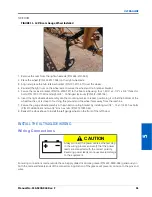
2. Disconnect the machine’s connectors from the battery terminals.
3. Install the power lead on the positive battery terminal and reinstall the machine’s battery connector.
4. Install the ground lead on the negative battery terminal and reinstall the machine’s battery connector.
CONNECT THE CONTROLLER (IF APPLICABLE) - GEN I CABLE ONLY
1. Locate the two console cables (P/N 115-0230-005) and connect them to the AutoBoom console cable (P/N
063-0130-021).
2. Make the necessary CAN connections. Keep in mind there should be only two CAN terminators in the system,
one installed at each end of the CAN bus.
Summary of Contents for RoGator 64 Series
Page 9: ...2 Manual No 016 0230 044 Rev F 5 INTRODUCTION ...
Page 10: ...CHAPTER 2 6 RoGator 64 74 86 SS Series AutoBoom Installation Manual ...
Page 21: ...3 Manual No 016 0230 044 Rev F 17 POWERGLIDE POWERGLIDE HYDRAULIC SCHEMATIC ...
Page 48: ...CHAPTER 4 44 RoGator 64 74 86 SS Series AutoBoom Installation Manual GEN II CABLING ...
Page 61: ...5 Manual No 016 0230 044 Rev F 57 ULTRAGLIDE ULTRAGLIDE HYDRAULIC SCHEMATIC ...
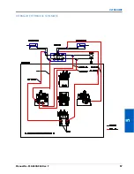
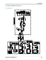
Page 71: ...Manual No 016 0230 044 Rev F 67 ULTRAGLIDE ULTRAGLIDE WIRING SCHEMATIC GEN I CABLING ...
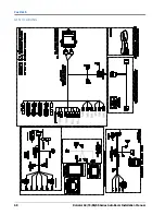
Page 72: ...CHAPTER 5 68 RoGator 64 74 86 SS Series AutoBoom Installation Manual GEN II CABLING ...
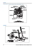
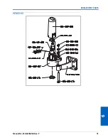
Page 75: ...6 Manual No 016 0230 044 Rev F 71 REPLACEMENT PARTS SENSORS ...
Page 76: ...CHAPTER 6 72 RoGator 64 74 86 SS Series AutoBoom Installation Manual ...

