C
HAPTER
5
60
RoGator 64/74/86/SS Series AutoBoom Installation Manual
INSTALL THE GAUGE WHEELS - OPTIONAL
GAUGE WHEEL MOUNTING LOCATIONS
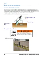
Wheel mounting locations may be influenced by the boom configuration. Determine the appropriate location for
mounting the wheels on the boom, ensuring the wheels will not interfere with or be damaged while folding or
unfolding the booms. Mount the wheels outside of the boom fold but inside of the boom breakaway.
MOUNT THE GAUGE WHEELS
90’ - 100’ BOOM
NOTE:
The appearance of the wheel axles may vary, depending on the type of wheel axle kit that was
ordered.
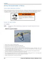
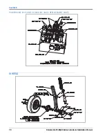
FIGURE 10. Gauge Wheel Installed
1. Remove the nuts from the left wheel axle.
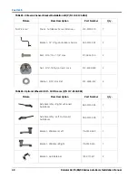
2. Place the wheel (P/N 322-0131-003) on the wheel axle.
3. Reinstall the lug nuts on the wheel axle to secure the wheel.
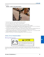
4. Mount the receiver bracket (P/N 116-0159-609) to the front of the left boom using two 1-9/16” W x 2-1/2” L x 3/
8” thread U-bolts (P/N 107-0171-611), two 2-1/16” W x 3” L x 3/8” thread U-bolts (P/N 107-0171-609), and eight
3/8”-16 zinc flanged lock nuts (P/N 312-1001-164).
5. Insert the wheel axle into the receiver bracket, positioning it so that the bottom of the wheel touches the
ground (or nearly so) and the wheel faces away from the machine.
6. Secure the gauge wheel assembly in the wheel mounting bracket by installing two 1/2”-13 x 1-1/2” SS hex bolts
(P/N 311-0058-186) and two 1/2”-13 zinc hex nuts (P/N 312-1001-043).
7. Repeat the steps above to install the right wheel.
WARNING
The machine must remain stationary and
switched off, with the booms unfolded and
supported, while installation or maintenance is
conducted.
Summary of Contents for RoGator 64 Series
Page 9: ...2 Manual No 016 0230 044 Rev F 5 INTRODUCTION ...
Page 10: ...CHAPTER 2 6 RoGator 64 74 86 SS Series AutoBoom Installation Manual ...
Page 21: ...3 Manual No 016 0230 044 Rev F 17 POWERGLIDE POWERGLIDE HYDRAULIC SCHEMATIC ...
Page 48: ...CHAPTER 4 44 RoGator 64 74 86 SS Series AutoBoom Installation Manual GEN II CABLING ...
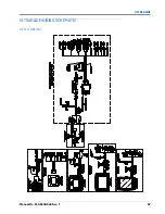
Page 61: ...5 Manual No 016 0230 044 Rev F 57 ULTRAGLIDE ULTRAGLIDE HYDRAULIC SCHEMATIC ...
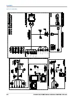
Page 71: ...Manual No 016 0230 044 Rev F 67 ULTRAGLIDE ULTRAGLIDE WIRING SCHEMATIC GEN I CABLING ...
Page 72: ...CHAPTER 5 68 RoGator 64 74 86 SS Series AutoBoom Installation Manual GEN II CABLING ...
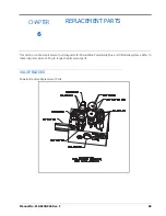
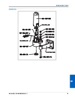
Page 75: ...6 Manual No 016 0230 044 Rev F 71 REPLACEMENT PARTS SENSORS ...
Page 76: ...CHAPTER 6 72 RoGator 64 74 86 SS Series AutoBoom Installation Manual ...

